Burnham 8H User Manual
Page 36
36
1. Standing Pilot (24) Sequence of Operation
a. Normal Operation
i. Thermostat or operating control calls for
heat. Vent Damper (if used) opens.
ii. Gas valves are energized allowing main gas
flow and ignition of main burners.
iii. Call or heat ends. Gas valves are de-
energized, extinguishing main flame. Vent
Damper (if used) closes.
b. Safety Shutdown
i. Limit: Automatically interrupts main burner
operation when water temperature exceeds
set point. Maximum allowable temperature
is 250°F. Circulator continues to operate
with call for heat, Vent Damper (if used)
closes. Normal operation resumes when
water temperature falls below set point.
ii. Blocked Vent Switch: Automatically
interrupts main burner operation when
excessive flue gas spillage occurs.
Circulator continues to operate and Vent
Damper (if used) remains open with call
for heat. If blocked vent switch is activated
do not attempt to place boiler in operation.
Correct cause of spillage and reset blocked
vent switch.
iii. Flame Roll-out Switch: Automatically
interrupts main burner operation when
flames or excessive heat are present in
vestibule. Circulator continues to operate
and Vent Damper (if used) remains open
with call for heat. Control is single use
device. If flame roll-out switch is activated,
do not attempt to place boiler in operation.
Correct cause of spillage and replace flame
roll-out switch.
iv. Thermocouple: Senses pilot flame and
causes gas valves to turn off main burner
and pilot burner gas flow should pilot burner
flame extinguish. Circulator continues to
operate and Vent Damper (if used) remains
open with call for heat.
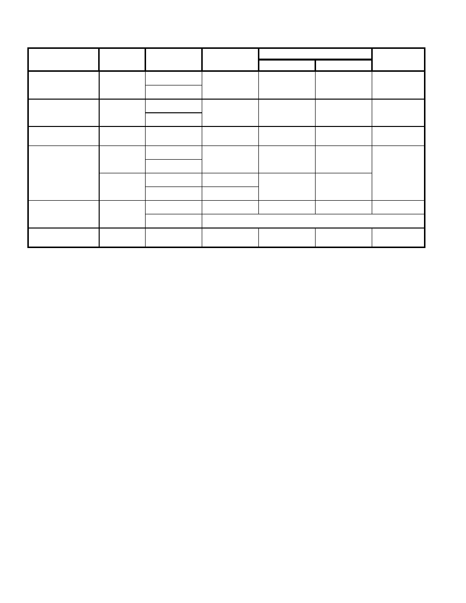
Table 10: Sequence of Operation and Wiring Diagrams
Ignition System
Country
Fuel
Boiler Sizes
Wiring Diagram Figure
Sequence of
Operation
Continuous
Intermittent
Standing Pilot (24V)
USA &
Canada
Natural Gas
6 & 7 Sect.
Figure 29
Figure 30
Page 36
LP Gas
Standing Pilot
(OP - 120V)
USA &
Canada
Natural Gas
6 - 10 Sect.
Figure 31
Figure 32
Page 39
LP Gas
Standing Pilot
(OP-CSD-1 - 120V
USA
LP Gas
8 - 10 Sec.
Figure 31
Figure 32
Page 39
Intermittent Ignition
(Honeywell EI - 24V)
USA
Natural Gas
5 - 10 Sect.
Figure 33
Figure 34
Page 42
LP Gas
Canada
Natural Gas
5 - 10 Sect.
Figure 35
Figure 36
LP Gas
5 - 7 Sect.
Intermittent Ignition
(EP - 120V)
USA &
Canada
Natural Gas
6 - 10 Sect.
Figure 37
Figure 38
Page 47
LP Gas
Not Available
Intermittent Ignition
(EP-CSD-1 - 120V)
USA
Natural Gas
8 - 10 Sect.
Figure 37
Figure 38
Page 47