V. gas piping warning, Warning, Notice – Burnham 8H User Manual
Page 29
2
V. Gas Piping
WARNING
Failure to properly pipe gas supply to boiler may
result in improper operation and damage to the
boiler or structure. Always assure gas piping is
absolutely leak free and of the proper size and
type for the connected load.
An additional gas pressure regulator may be
needed. Consult gas supplier.
A.
Size gas Piping. Design system to provide adequate gas
supply to boiler. Consider these factors:
1. Allowable pressure drop from point of delivery to
boiler. Maximum allowable system pressure is ½
psig. Actual point of delivery pressure may be less;
contact gas supplier for additional information.
Minimum allowable gas valve inlet pressure is
indicated on rating label.
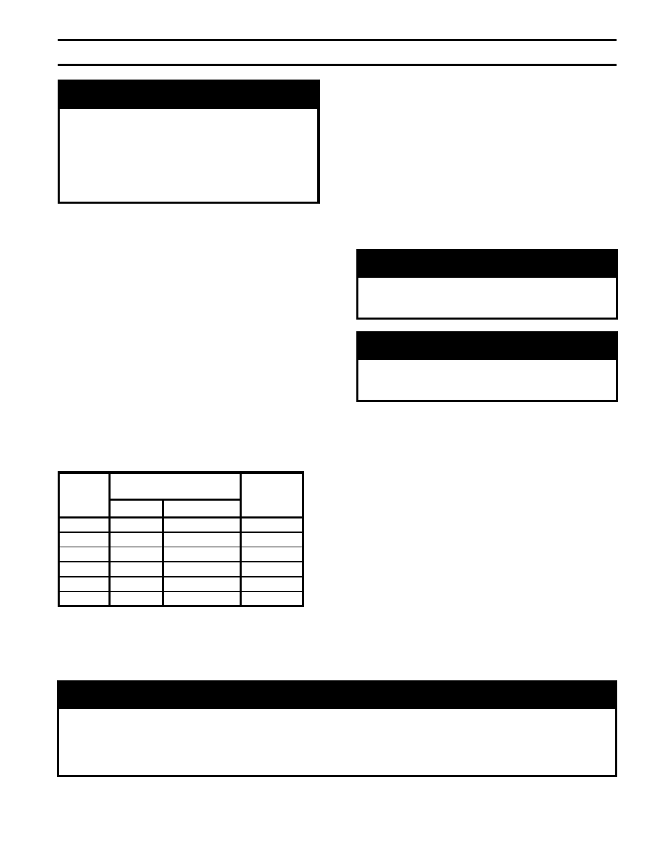
2. Maximum gas demand. Table 5 lists boiler input
rate. Also consider existing and expected future gas
utilization equipment (i.e. water heater, cooking
equipment).
3. Length of piping and number of fittings. Refer to
Table 6 for maximum capacity of Schedule 40 pipe.
Table 7 lists equivalent length for standard fittings.
Boiler
Model
Rated Capacity
(cubic feet per hour)
Gas
Connection
Size
Natural
LP / Propane
805H
252
100.8
1
806H
315
126
1
807H
374
149.6
1
808H
433
173.2
1
809H
491
196.4
1
810H
550
220
1
Table 5: Rated Input
4. Specific gravity of gas. Gas piping systems for
gas with a specific gravity of 0.70 or less can be
sized directly from Table 6, unless authority having
jurisdiction specifies a gravity factor be applied.
For specific gravity greater than 0.70, apply gravity
factor from Table 8. If exact specific gravity is not
shown choose next higher value.
For materials or conditions other than those listed
above, refer to the National Fuel Gas Code,
NFPA 54/ANSI Z223.1 and/or CAN/CSA B149.1
Installation Codes, or size system using standard
engineering methods acceptable to authority having
jurisdiction.
WARNING
Failure to use proper thread compounds on all
gas connectors may result in leaks of flammable
gas.
WARNING
Gas supply to boiler and system must be
absolutely shut off prior to installing or servicing
boiler gas piping.
B.
Connect boiler gas valve to gas supply system.
1. Use methods and materials in accordance with local
plumbing codes and requirements of gas supplier. In
absence of such requirements, follow the National
Fuel Gas Code, NFPA 54/ANSI Z223.1 and/or
CAN/CSA B149.1 Installation Codes.
2. Use thread (joint) compound (pipe dope) resistant to
action of liquefied petroleum gas.
3. Install sediment trap, ground-joint union and manual
shut-off valve upstream of boiler gas valve and
outside jacket. See Figure 24.
4. All above ground gas piping upstream from
manual gas valve must be electrically continuous
and bonded to a grounding electrode. Do not use
gas piping as a grounding electrode. Refer to the
National Electrical Code, ANSI/NFPA 70 and/or
CSA C22.1 Electrical Code.
NOTICE
USA boilers built for installation at altitudes greater than 2,000 feet above sea level have been specially
orificed to reduce gas input rate 4 percent per 1,000 feet above sea level per the National Fuel Gas Code,
NFPA 54/ANSI Z223.1, Section 8.1.2 and Appendix F. Canadian boilers’ orifice sizing is indicated on the
rating label. High altitude boiler models are identifiable by the model number’s tenth digit on the rating label.
(4=2000’ - 4500’, 5= 2000’ - 5000’)