Flowbar iom, Step 2. make inlet duct connections, Step 3. install drywall ceiling – Titus FlowBar IOM User Manual
Page 8
8
Installation Manual - FlowBar
FlowBar IOM
Redefine your comfort zone. ™ | www.titus-hvac.com
FlowBar Installed After Hard Ceiling Installation
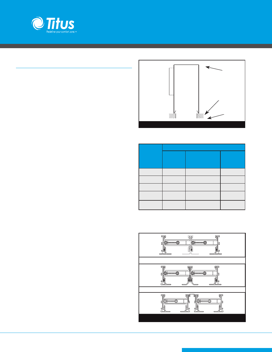
STEP 1. Install Plenums
̷ Install Titus model FBP or FBPI Plenum and secure to the building
structure using hanger wire.
̷ If Plenum is furnished by others, a hemmed edge inside the bottom
of the Plenum sides is required to capture the hanger bracket
assemblies.
̷ The Plenum should be hung so that the Plenum straddles the ceiling
opening and the bottom edge of the Plenum rests on the backside
of the ceiling as shown in Figure 11.
[FlowBar PlenumCF]
Last edited: 6-23-99
Last edited by: TVDR
STEP 2. Make Inlet Duct Connections
̷ Attach the Inlet Duct to the inlet collar using the method prescribed
by the job specification.
̷ NOTE: If the Plenum Inlet is accessible after the ceiling is installed,
this step can be completed later.
STEP 3. Install Drywall Ceiling
̷ The ceiling contractor can now frame in the ceiling around the
Plenum and install the drywall. Complete the ceiling surfacing.
̷ NOTE: The finished opening must be smaller than the overall
FlowBar face dimensions. Refer to Table 2 for the ceiling opening
width required. The Two-Slot Diffusers are available with the three
different types of center extrusions as shown in Figure 12. The type
of center extrusion determines the ceiling opening.
FlowBar
Model
Ceiling Opening Width
1-SLOT
2-SLOT
2CRA & 2CRB
2-SLOT
2CRN
FL-10
3
5
½
6
3
⁄
8
FL-15
4
7
½
8
3
⁄
8
FL-20
5
9
½
10
3
⁄
8
FL-25
6
11
½
12
3
⁄
8
FL-30
7
13
½
14
3
⁄
8
Table 2. Ceiling Opening Dimensions for Border Type 77
[FlowBar CRA]
Last edited: 4-26-99
Edited by: TVDR
[FlowBar CRB]
Last edited: 4-26-99
Edited by: TVDR
Edited by: JLM
Last edited: 7-8-98
[745b]
Attach hanger
wire
to plenum clips
Hemmed Edge
of Plenum
Ceiling
Opening
Ceiling
CRA
CRB
CRN
Figure 11. Concealed Fastening Plenum Installation
Figure 12. Center Extrusion Configurations