Flowbar iom, Flowbar installed during hard ceiling installation – Titus FlowBar IOM User Manual
Page 7
7
Installation Manual - FlowBar
FlowBar IOM
Redefine your comfort zone. ™ | www.titus-hvac.com
STEP 8. Review Installation - (Borders 22 & 55 Only)
Before continuing it is recommended that the installer confirm that:
̷ The FlowBar Diffuser is secure and straight.
̷ For units longer than twelve feet, a 1/8” gap between sections is
recommended to allow for thermal expansion.
̷ Do not run the HVAC system during the finishing procedures. This
could cause premature drying of the compounds, making them
more prone to cracking.
STEP 9. Finish the Surface - (Borders 22 & 55 Only)
̷ Sand the finishing surface with medium grit sandpaper in order to
rough up the surface for good joint compound adhesion.
̷ Remove dust from finishing surface following sanding with a tacky
cloth. Or clean with a mild cleaner/degreaser.
̷ Apply first coat of joint compound onto the diffuser’s finishing flange
and onto the sheetrock three inches. Use a durabond setting-type
compound.
̷ Embed a 4” wide mesh or paper tape into the first coat of joint
compound. Smooth to remove air pockets. The tape should cover the
aluminum rail, but not extend over the raised lip on the rail. Apply
second coat of finishing compound over the tape and smooth.
̷ After compound has dried, apply two coats of standard finishing
compound and let dry. Sand smooth, prime, and paint as scheduled.
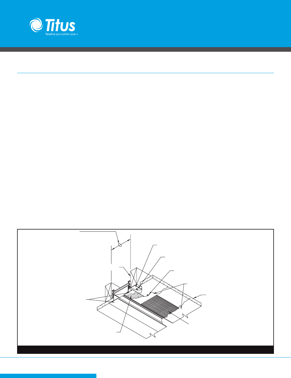
Framing Member
Finishing Flange
Joint Compound
4" wide mesh tape
Bonding Agent
Screw through drywall into
ceiling frame every 12"
Hard Ceiling Clips to be located every 10"
Screw Hard Ceiling Clips to ceiling frame
Ceiling frame opening width (W) shown in Table 1
Drywall
Hard Ceiling Clips to be located every 10”
Screw Hard Ceiling Clips to ceiling frame
Screw through drywall into ceiling frame every12”
JOINT COMPOUND
DRYWALL
SAND THIS SURFACE
FINISHING FLANGE
FRAMING MEMBER
Ceiling Frame opening
Width (W) shown in Table 1
FlowBar Installed During Hard Ceiling Installation
Figure 10. Summary of Border Type 22 Installation