Titus Dual Duct Terminal IOM User Manual
Installation manual, Dual duct vav terminals
Installation Manual
DD-IOM-1.0
6-15-02
Dual Duct VAV Terminals
Receiving Inspection
After unpacking the terminal, check it for
shipping damage. If any shipping
damage is found, report it immediately
to the delivering carrier. Store units in a
clean, dry location prior to installation.
Caution: Do not use the flow sensor,
connecting tubing, or damper shaft
linkage as a handle to lift or move
assembly. Damage to the flow sensor
or controls may result.
Supporting the Assembly
Dual duct terminals are not light enough
to be supported by the duct work itself.
The terminal should be supported
directly. Straps screwed directly into the
side of the terminal, threaded rod
through the optional hanger brackets
(see Figure 1), or the method prescribed
for the rectangular duct on the job
specifications may be used. The bottom
should be left clear where there are
access panels.
Important: If equipped with pneumatic
controls, the terminal must be mounted
right side up. It must be level within
+ or - 10 degrees of horizontal, both
parallel to the air flow and at the right
angle of air flow. The control side of the
terminal is labeled with an arrow
indicating UP. The first letter of the
model number (P) indicates pneumatic
controls. Most electronic units (A-analog
controls and D-digital controls) can be
installed in any orientation. Check with
the local TITUS representative for
verification.
Duct Connections
Slip each inlet duct over the inlet collar
of the terminal. Fasten and seal the
connection by the method prescribed by
the job specification.
The diameter of the inlet duct "D" in
inches must be equal to the listed size
of the terminal; e.g. a duct that actually
measures 8 inches must be fitted to a
size 8 terminal. The inlet collar of the
terminal is made 1/8 inch smaller than
listed size in order to fit inside the duct
(see Figure 1). The supply ductwork
must be insulated up to the face of the
terminal unit even if inlet adapters are
used.
Note:
Do not insert duct work inside
the inlet collar. Inlet duct should be
installed in accordance with SMACNA
guidelines.
The outlet end of EDV and MDV series
units are designed for use with slip and
drive duct connections. A rectangular
duct the size of the terminal outlet
should be attached.
If single-point electronic velocity sensors
are used, 3 to 5 inlet duct diameters of
straight duct should be provided at the
terminal inlet; for specific guidelines,
consult the control manufacturer’s
installation guidelines. Sensor(s) may be
attached to th e i n s i d e o f c o n t r o l
enclosure for protection during shipping.
Sensors must be inserted in inlets and/
or discharge duct of terminal before
operating. Remove any protective
plastic devices from tip of sensor before
installation.
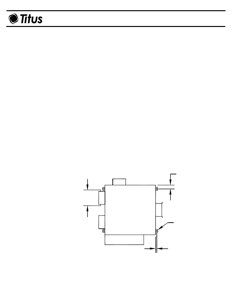
Figure 1. Dual Duct Recommended Hanger Bracket Locati ons
Hanger Bracket
Location or
Hanger Strap
2" Typical
1/2"
D
Option.