Skyjacker T422 User Manual
Page 6
11. Install driver side differential drop bracket using OEM bolts in
two bottom holes. Apply loctite and torque to 70 Ft. Lbs. Use
1/2” x 1 1/2” hex bolts, washers, and lock nuts in two upper
holes. Torque to 85 Ft. Lbs. (See Photo #11).
12. Remove tie rods from steering knuckles. Remove two bolts on
back side (inside) of spindle which hold the metal bracket for
the brake hose.
13. Support lower A-Arms with floor jack and separate upper ball
joint from spindle. Using file, file corners off OEM spindle to
contour with bottom of new spindle adapter so that the bottom
of the new spindle seat surface is in contour with OEM
spindle top surface. Clean out hole on top of steering
knuckle (spindle).
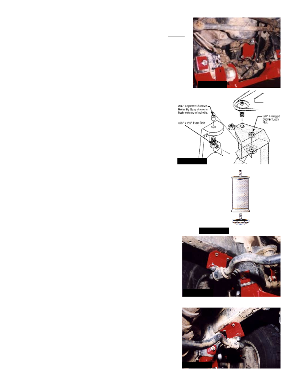
14. As shown in Photo #12, insert tapered spindle sleeves
with small end downward. Be sure tapered sleeves are
flush with top of spindle (if necessary tap with a hammer,
or file down to be flush). Place new spindle adapters
onto original spindles, and install 5/8” x 2 1/2” hex bolts
and 5/8” flanged stover lock nuts.
Note: Be sure to use
the special black Grade 8 Flanged Stover Lock Nut
supplied! Torque to 150 Ft. Lbs. Insert upper ball joints
into new spindle adapters and torque to 105 Ft. Lbs.
Reinstall tie rods, and torque to 67 Ft. Lbs. Next reinstall brake
hose brackets to bottom of new spindle adapters using OEM
bolts (apply loctite). Be sure to install cotter pins.
15. Slightly file original bump stop mounting lips on each side (only
the front two) for shock clearance. Install new Skyjacker shocks.
16. Attach new polyurethane bump bump stops to new bump stop
spacers. Then install bump stop spacers to original mounts with
3/8” coarse thread lock nuts. See Photo #13.
17. Install the two new sway bar drop down brackets to frame using
OEM hardware, but adding a 5/16” flat washer under bolt
heads. Install sway bar to bottom of new drop down brack-
ets using new 5/16” x 1” bolts, 5/16” flat washers ( 1 under
bolt heads and 1 under nuts) and 5/16” lock nuts. Torque
all bolts to 25 Ft. Lbs. See Photo’s #14 and #15 (open
side goes inward with slant down and toward the front).
Tighten A-Arm end of sway bar.
IT422/432
Pg 6
Photo #11
Photo #12
Photo #13
Photo #14
Photo #15