Chapter 6: pump control, How it works—float switches – Sensaphone CELL682 User Manual
Page 43
41
Chapter 6: pump Control
ChapTer 6: pump ConTrol
The Cell682 can be used in Fill or Drain pump control applications using either
float switches or an analog level transducer. When used with Float Switches, dry
contact inputs #6-8 have a dedicated special function (see below):
Pump Control using Float Switches
Dry Contact Input #6 – Lead pump float switch
Dry Contact Input #7 – Lag pump float switch
Dry Contact Input #8 – Pumps-off float switch
When performing pump control using an analog level transducer (4–20mA), ana-
log input #6 is designated as the well level input.
Note: Only normally-open float switches can be used for pump control (e.g. the
switch is open when no water is present).
how it works—float switches
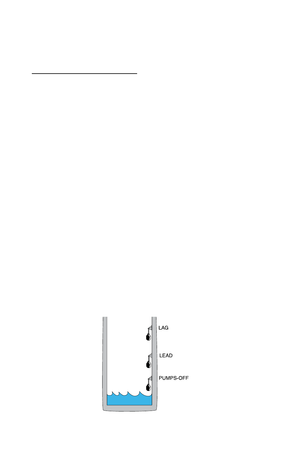
When performing drain pump control using float switches, three floats are
required: Lead, Lag, and Pumps-Off (see Fig 1). The Lead float determines when
to turn on the first pump. If the first pump is unable to bring the level below the
Pumps-Off float, then the Lag float will close, turning on the second pump. When
the level drops below the Pumps-Off float, both pumps are turned off. If any of the
floats get stuck (i.e. the lead and pumps-off floats closed, or the lag and pumps-off
floats closed) then both pumps will be turned on and an alarm will be tripped on
the output or outputs in question. In duplex mode, the Cell682 will automatically
alternate between the two pumps to facilitate uniform run time between the two.
If only one relay output is set to pump-control mode, then simplex control is per-
formed. In Simplex mode only the Lead float (Dry Contact #6) and Pumps-Off
float (Dry Contact #8) are required. Either output relay can be used in simplex
mode.
Figure 1: Float positions for a drain application