Sensaphone CELL682 User Manual
Page 27
25
Chapter 2: Installation
ground. This is particularly important for sensor wires that are run in conduit
with other noise-generating conductors, such as 60Hz AC. It is strongly recom-
mended that input wiring be run in a conduit separated from AC power or output
wiring. When wire runs are long or are in close proximity to large power consum-
ing, power generating, or power switching equipment, it is highly recommended
that shielded wire be used.
Also, be sure to use the appropriate gauge wire based on the distance and sensor
type. See chart below:
Wire Gauge Thermistor
NO/NC Contact & 4–20mA
#24
250’
1000’
#22
500’
2000’
#20
1000’
4000’
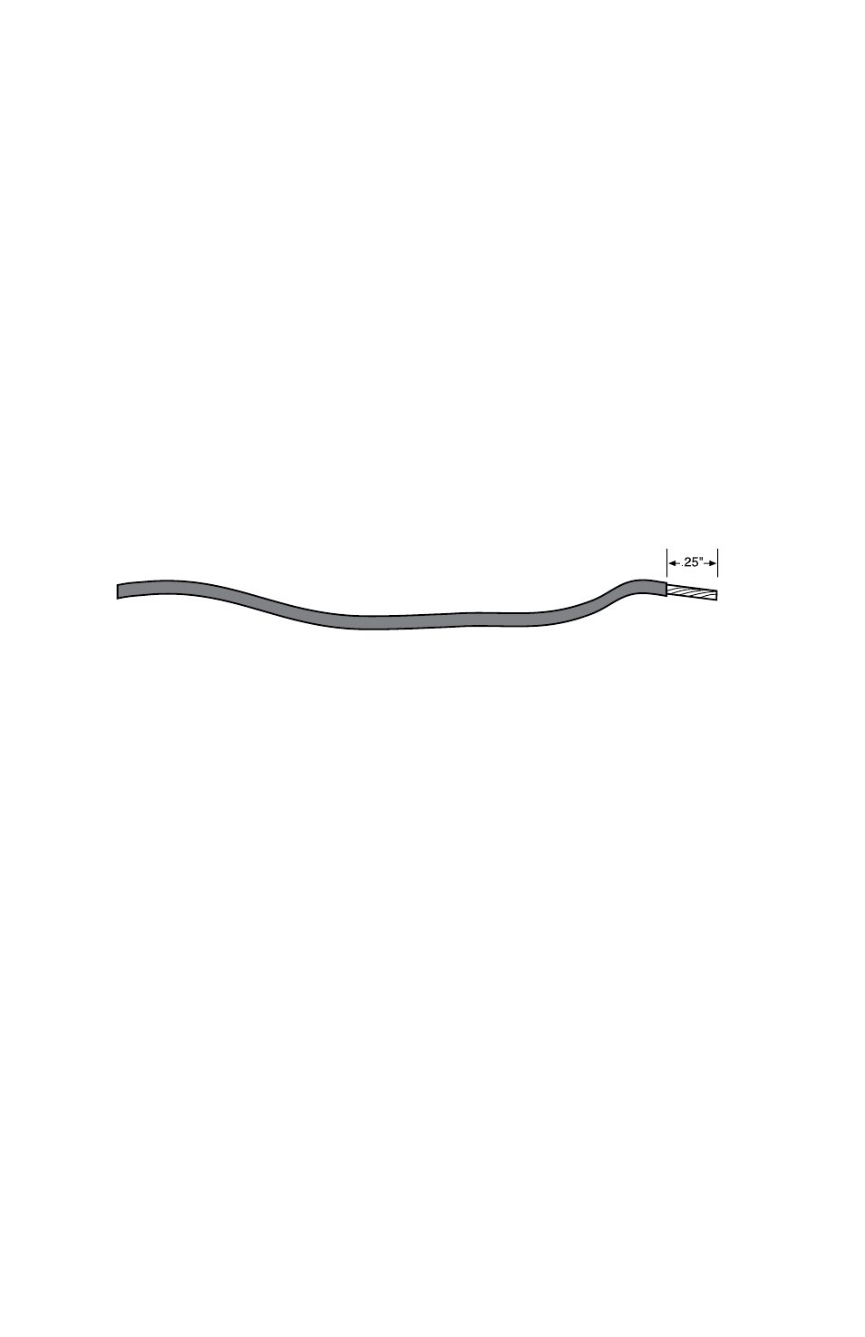
When preparing wire for connection to the terminal blocks, strip 1⁄4” of insulation
from the conductor (see figure below).
Figure 11: Wire stripped for connection
NOTE: All wiring should comply with Section 17 of the UL requirements.
Led INdICaTors
The LEDs provide on-site alarm and status information. Listed below are descrip-
tions of how the LEDs work.
aLarm:
LED Off: No alarms
LED Blinking: Unacknowledged alarm exists
LED On: Acknowledged alarm exists
reGIsTered:
LED Off: Not registered (unit not activated)
LED Blinking: Cell682 is sending or receiving messages
LED On: Registered
IN raNGe:
LED Off: Not in range of wireless network
LED On: In range of wireless network