Chapter 7: wireless sensors 39 – Sensaphone WSG30 System Users manual User Manual
Page 39
Chapter 7: Wireless Sensors
39
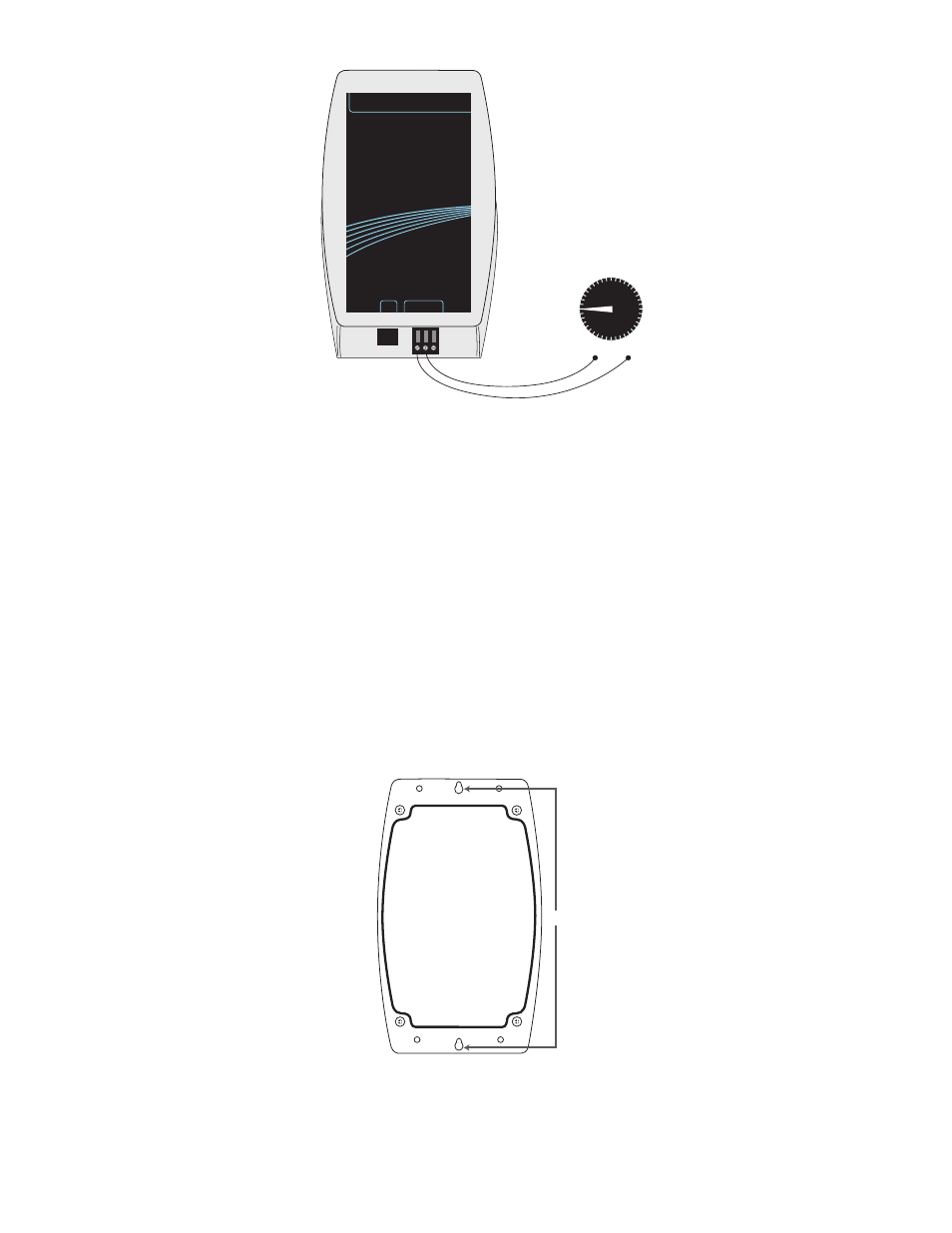
Self–Powered
4-20mA Transducer
+
–
4-20mA
Output
Ground
SENSAPHONE
®
REMOTE MONITORING SYSTEM
WIRELESS SENSOR GATEWAY
4-20mA
SENSOR
5VDC
GND
|
mA
|
24VDC
4-20mA sensor with self–powered transducer
Battery InstallatIon
Remove the four screws on the bottom of the enclosure. Carefully separate the top of the enclosure from
the bottom. Locate the three battery clips on the circuit board. Take note of the polarity markings iden-
tifying the positive and negative ends of the batteries. Install the batteries in the clips. Re-attach the top
and bottom cover with the four screws.
MountIng
The 4-20mA sensor can be mounted directly on a flat surface. Consideration should be given as to
whether or not an electrical outlet will be required if using the optional power supply. Mount the sensor
as high as possible to provide for optimal Wireless transmission. When installed within a building where
the Wireless signal must travel through several obstructions, the sensor should be located within 300’ of
the WSG30 or within 300’ of a sensor/router.
Use a pencil to mark the hole locations at the top and bottom of the housing. Install the drywall anchors
(if necessary) to the wall. Attach the housing to the wall using #6 tapping screws.
6.125”