Unloading & assembly – MacDon 5010 Mower Conditioner User Manual
Page 75
73
UNLOADING & ASSEMBLY
ATTACH HYDRAULICS AND ELECTRICAL
(continued)
4. Attach motor to header primary drive, cont’d:
* See previous page for illustrations and photos.
d) Attach torque arm (H) to motor:
- Orient torque arm with 21/32" (17 mm)
dimension as shown.
- Position free end of arm to achieve dimension
(S) = 8.75" (222 mm) and torque hex nut (J) to
50 ft.lbs. (68 N
⋅m), then securely tighten lock
nut (K) against hex nut.
e) Reattach torque arm (H) to frame, tightening
hardware as in step 4d.
f) Reattach support bar to frame with bolts
(removed in step 4a). Attach motor hoses and
wiring harness to support between holders (M,
see photo next page). To avoid damage to
hoses and harness, do not over-tighten holder
hardware.
g) Re-tighten hose fittings on motor.
h) Replace adjustment rod (removed in step 4a)
and secure with spring pin. Adjust "Roll Gap" as
described in Operation section, or adjust to
dimension measured in step 4a.
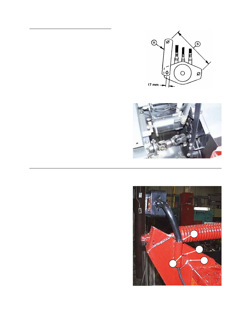
5. Attach lights as follows:
a) Install one 5/16 NC x 1/2” screw (A) into the
pre-drilled hole in the light support tube.
b) Insert light support tube through welded tube
on header frame.
c) Install one 3/8 NC x 3/4” hex head bolt (B)
and one 3/8” NC hex nut (C).
NOTE: Tighten bolt (B) to secure light firmly.
Do not overtighten bolt. Light must be able to
be turned with minimal force. Lock jam nut
(C) against tube to secure the position.
d) Install one 1/4 NC x 5/8” hex head bolt (D),
along with one 1/4” NC lock washer through
ground wire eyelet, and attach through frame
using one 1/4” NC lock nut.
ATTACHING LIGHTS
B
D
A
C
ORIENTATION OF TORQUE ARM TO MOTOR
MOTOR INSTALLED