Unloading & assembly – MacDon 5010 Mower Conditioner User Manual
Page 74
72
UNLOADING & ASSEMBLY
ATTACH HYDRAULICS AND ELECTRICAL
(continued)
4. Attach motor to header primary drive:
NOTE: For easier installation of motor onto
shaft, hoses may be completely removed from
motor at swivel fittings. A minimal amount of oil
will drip out, however extreme care must be
taken to prevent dirt from entering at hose ends
and motor ports. If removing hoses, go to step
(c).
a) Complete the following steps to increase
clearance for motor installation:
− Before lowering header, remove spring pin (A)
at L/H roll gap adjustment rod.
− Lower header to ground: Connect the two lift
cylinder hoses (T) to tractor so that when the
tractor control is moved back, the lift cylinder
will extend, raising the header. When the
tractor control is moved forward, the lift
cylinder will retract, lowering the header. Move
the lift cylinder stops to storage position (U)
and lower header. Before header will lower,
cycle the control up and down a few times to
fill lines. It may be necessary to loosen float
springs to allow header to lower.
− Rotate conditioner rolls so that keyway slot in
drive shaft is at the top. Remove roll gap
adjustment rod (B) as follows:
Measure exposed thread at top of rod and
record for reassembly.
Unscrew adjustment tube (L) from rod (B).
Remove rod (B) from left support arm (C).
− Remove two bolts (N) securing support bar to
frame and pivot the bar rearward.
− Remove torque arm (H) from header frame.
b) Loosen fittings on motor about 1/2 turn to allow
hoses to swivel.
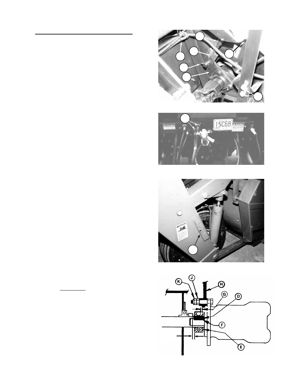
c) Install motor on drive shaft using key (D)
between two clamp halves (E):
- IMPORTANT: Push motor onto shaft so that
key (D) bottoms out in motor shaft keyway at
(F).
- If motor shaft will not slide into drive shaft bore,
use a large screwdriver or bar to spread the
drive shaft keyway.
- When positioning motor for installation, motor
hoses should be in cut-out (P) in frame.
- Position clamps for 1/4" (6 mm) clearance (G)
between clamp and bearing lock collar (when
installed in step d).
- Torque clamp bolts to 75 ft.lbs. (100 N
⋅m).
6 mm
(1/4”)
INSTALL MOTOR & ATTACH TORQUE ARM
REMOVE ROLL GAP ADJUSTMENT ROD
R
B
A
C
P
L
N
ATTACH HEADER LIFT HOSES
T
CYLINDER STOP STORAGE
U