Header attaching & detaching – MacDon 871 Combine Adapter User Manual
Page 8
8
HEADER ATTACHING & DETACHING
ATTACHING HEADER TO COMBINE AND ADAPTER
(continued)
8. Make the hydraulic line connections:
Reel drive pressure and return lines:
Connect two hoses between header and
combine.
Reel lift line: Connect one hose between
header and combine.
Draper drive pressure and return lines:
Connect two hoses between header and
adapter.
NOTE: As an aid in connecting hydraulics, the
following colour coding has been used:
ORANGE - Draper Drive Pressure
BLUE - Draper Drive Return
YELLOW - Reel Drive Return
Reel fore-aft lines (if equipped): Connect two
hoses between header and combine.
9. Connect wiring harness between header and
combine. NOTE: A harness adapter is supplied
with adapter completion package.
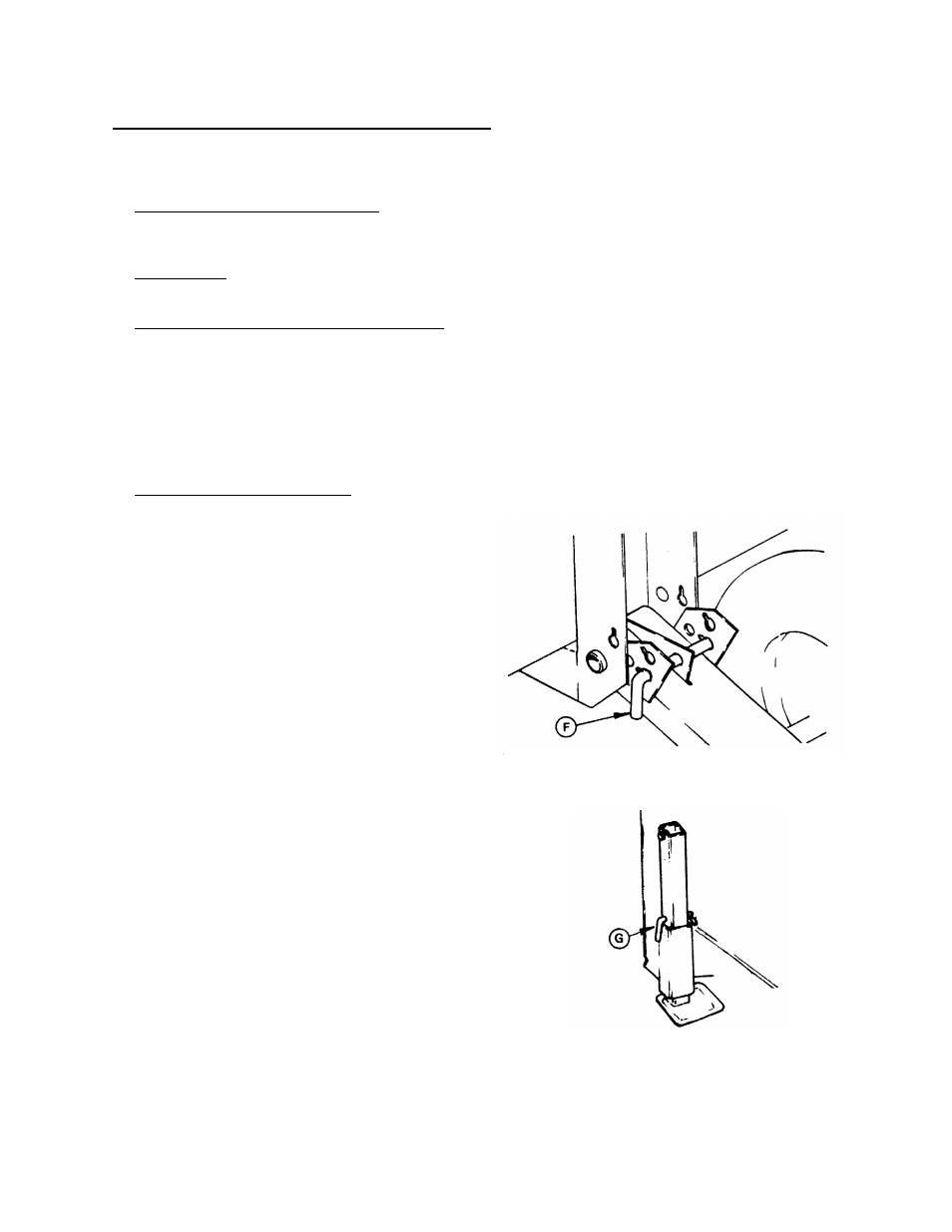
10. For headers with gauge wheels, remove pins at
gauge wheels and place in field position (F).
See “Cutting Height” in Header Operator’s
Manual to choose between alternate field
positions. (For headers with gauge
wheel/transport option, gauge wheel support is
not exactly as illustrated. See decal at support.)
NOTE: Rotate pin to align roll pin with key slot
for removal and installation. Roll pin locks
inside to secure the position.
11. For headers without gauge wheels, raise
header stand to storage position (G).
12. Place 8" (200 mm) block under front of adapter
feeder pan. Ensure all feeder pan-to-cutterbar
anchors are removed or turned sideways to
prevent damage to anchors when cutterbar is
lowered. Adjust feed pan fully forward for initial
setting. (See next page.)
13. Disengage header lift cylinder stops and slowly
lower header until adapter feeder pan rests on
block, and cutterbar rests on feeder pan.
GAUGE WHEELS - FIELD POSITION
HEADER STAND - STORAGE POSITION