Operation – MacDon 871 Combine Adapter User Manual
Page 16
16
OPERATION
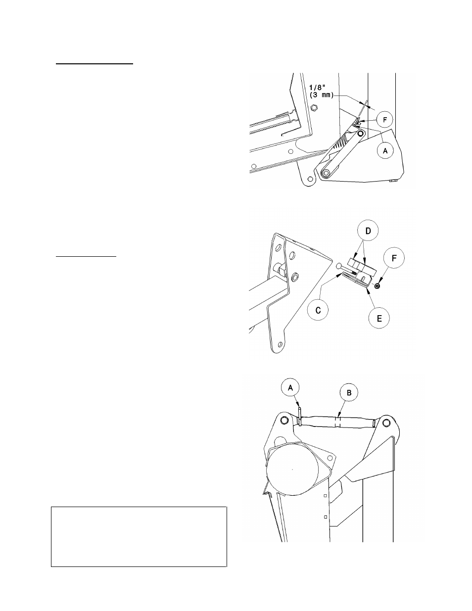
HEADER LEVELLING
Adjust header levelling with header at the flattest
angle. See Header Angle, below.
1. With header on level ground, lower header so
cutterbar is 2 to 4 inches (50 to 100 mm) off the
ground.
2. Check level of header by measuring cutterbar to
ground at both ends.
3. To lower cutterbar on one end, remove a shim (C)
from between rubber pads (D) and angle (E).
Adjust shim quantity side to side, placing from 0
to 2 shims to level header. To add or remove a
shim:
•
Lower cutterbar to ground and continue lowering
feeder house so gap at (A) increases.
•
Remove nut (F) and add or remove shim(s) as
required.
•
Reassemble, maintaining 1/8 inch (3 mm)
between angle and float support as shown.
HEADER ANGLE
The header (or guard) angle can be adjusted from
15
°
to
20
°
below horizontal. (Actual angle may vary
with combine set-up.)
See Combine Operator’s Manual for header levelling
and additional header angle adjustments.
IMPORTANT: The flat header angle (15
°
) is
recommended for normal conditions. A flatter header
angle reduces sickle section breakage and reduces
soil scooping or build-up at the cutterbar in wet
conditions. Use a steeper angle to cut very close to
the ground, or in down crop for better lifting action.
IMPORTANT: Header flotation gets lighter as header
angle increases, and must be readjusted. See
"Header Flotation", on page 15.
To adjust header angle with mechanical link:
1. Lower cutterbar to ground and continue
lowering to drop feeder house another 2 to 5
inches (50 to 125 mm).
2. Back off the locking collar (A) on top link
turnbuckle.
3. Using a punch in hole in turnbuckle (B), turn to
adjust header angle.
Longer top link = steeper header angle
( = lighter float )
4. At desired adjustment, tighten locking collar (A)
securely against turnbuckle to fix the position.
HEADER ANGLE HYDRAULIC ADJUSTMENT
An optional kit is available which allows adjustment
of header angle from the combine cab by means
of a hydraulic cylinder.
See “Unloading and Assembly” section for
information on assembly and use of this option.
HEADER ANGLE MECHANICAL ADJUSTMENT