Dfm1000 wiring diagram – Opticon DFM 1000 User Manual
Page 9
U
SER
’
S MANUAL
DFM1000
9
For configuration of the DFM100 an additional
configuration kit is available. You are strictly
recommended to use this kit for optimaliza-
tion.
The scanner should work according to the
default options. Other options have to be set
by the user, through the optional configuration
kit.
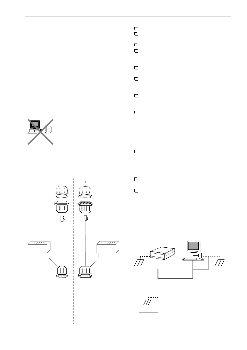
2.5.1 Power supply and
connection to the host.
The wiring diagram on this page gives some
suggestions to connect the scanner correctly.
Do not plug the DB25 male
connector of the scanner
directly into the RS232 or
parallel port from computer
(or printer). The pinout is not
compatible and will cause
damage without using an
adapter.
Connect the scanner to the host.
Connect power supply to the scanner
(9-33V DC unregulated + 5%)
Connect power to the host.
Scanner beeps.
Default setting; Power LED (back side
scanner) should light up in orange colour.
Scan an EAN/UPC bar code label from the
test labels in chapter 9.
Scanner beeps.
Default setting; Good Read LED (back side
scanner) flash green shortly.
Data is sent to the host.
Default communication settings:
RS232 (9600,N,8,1)
Check data at the host.
2.5.2 Grounding
See grounding diagram.
Make sure the shielding is grounded only
to earth ground at the host. The shielding
connection to the scanner from the host
should not be connected ot the shielding
of the scanner.
Make sure that the frame ground of the
scanner is connected to the earth ground.
Make sure that the host, the scanner and
their power supplies are connected to a
common earth ground.
COMPUTER:
- RS 232 port
- parallel port
DFM1000:
DB25 male
connector
9-33 V DC
DB25 MALE
(from scanner)
6P6
MOD.
JACK
TO PARALLEL
PORT OF PC
TO HOST
DB25
FEMALE
RS 232
ADAPTER
ALTERNATIVE
CONFIGURATION
MODE
DFM1000 Wiring Diagram
CONFIGURATION
ADAPTOR
DB25 MALE
(from scanner)
COMMUNICATION
AND CONFIGURATION
MODE
POWER
SUPPLY
9-33 V DC
POWER
SUPPLY
8P8
MOD.
JACK
DB9
FEMALE
EARTH GROUND
SHIELDING
COMMUNICATION CABLE
DFM1000 Grounding Diagram
SCANNER
HOST