Pin-out – Opticon DFM 1000 User Manual
Page 13
U
SER
’
S MANUAL
DFM1000
13
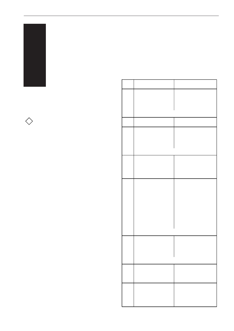
PIN-OUT
5
The pinout description mentioned in this chap-
ter must be used to connect the DFM1000
scanner to the host.
The pinout of the DB25 male
connector is NOT compatible with
standards for RS232.
Do not plug the DB25 male connector of the
scanner directly into the RS232 or parallel
port from computer (or printer). The pinout is
not compatible and will cause damage without
using an adapter.
!
PIN
1
2
3
4
5
6
7
8
9
10
11
12
13
14
15
16
17
18
19
20
21
22
23
24
25
COLOR
BROWN
RED
ORANGE
PINK
PIN 1 - 4 : RS485 INTERFACE
YELLOW
GREEN
LIGHT GREEN
BLUE
LIGHT BLUE
PIN 6 - 9 : RS232 INTERFACE
PURPLE
GREY
WHITE
BLACK
BROWN - BLACK
RED - BLACK
PIN 14 : FOR FUTURE EXPANSION
ORANGE - BLACK
PINK - BLACK
YELLOW - BLACK
GREEN - BLACK
PIN 16 - 19 : FOR FUTURE EXPANSION
LIGHT GREEN - BLACK
BLUE - BLACK
LIGHT BLUE - BLACK
PURPLE - BLACK
GREY - BLACK
WHITE - BLACK
FUNCTION
TR-
TR+
T-
T+
not connected
RTS
CTS
RxD
TxD
SUPPLY VOLTAGE
9-33 V DC UNREGULATED
(< 1 V
SIGNAL GROUND
(NO)READ OUTPUT
TTL - sink or source
max. 4mA
TRIGGER INPUT
High level voltage: 2-15 V
Low level voltage : 0-0.8 V
I/O 1
TRIGGER OUTPUT
TTL - sink or source
max. 4mA
I/O 2
I/O 3
I/O 4
I/O 5
I/OE 1
I/OE 2
I/OE 3
not connected
+5 V DC OUTPUT
(MAX. 100mA)
FRAME GROUND
p-p ripple)