Barco R9002327 User Manual
Page 50
INSTALLATION ADJUSTMENTS
INSTALLATION
ADJUSTMENTS
INSTALLATION ADJUSTMENTS
INSTALLATION
ADJUSTMENTS
7-17
7-17
5975069A BARCOVISION 708 200498
5975069A BARCOVISION 708 200498
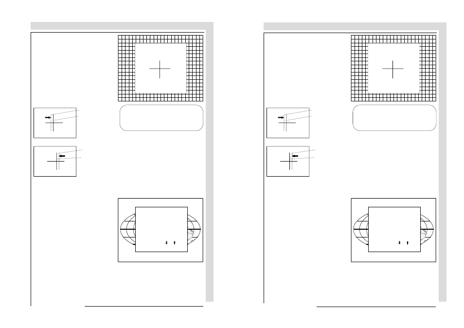
EXIT returns to the CRT projection angle
adjustment.
After finishing the installation adjust-
ments procedure, the 'Path selection'
blue crosshair
green crosshair
blue crosshair
green crosshair
Move the blue CRT
to the outside,
away from the
green CRT
Move the blue CRT
towards the green
CRT
returns on the screen. You are now
able to start the alignment procedure
for the projector. You have the choice
between :
- Guided Adjustment Procedure
- Random Access Adjustment Proce-
dure
The result of both procedures will be
the same. More explanation about both
procedures is given in the owners
manual.
The following page gives an overview
of the image corrections.
These screws fasten the cooling house
of the blue tube.
Pivot the blue CRT until the center of the
blue image coincides with the center of
the green image. If the angle of the red
CRT is corrected, tighten the four bolts.
ENTER continues to the path selection
menu.
CRT
PROJECTION ANGLE
ADJUSTMENT
Align crosshairs
Select with or
then
ADJUSTMENT MODE
Select a path from below :
GUIDED
RANDOM ACCESS
INSTALLATION
SERVICE
IRIS
Source 1