Barco R9002327 User Manual
Page 49
INSTALLATION ADJUSTMENTS
INSTALLATION ADJUSTMENTS
7-16
INSTALLATION
ADJUSTMENTS
7-16
INSTALLATION
ADJUSTMENTS
5975069A BARCOVISION 708 200498
5975069A BARCOVISION 708 200498
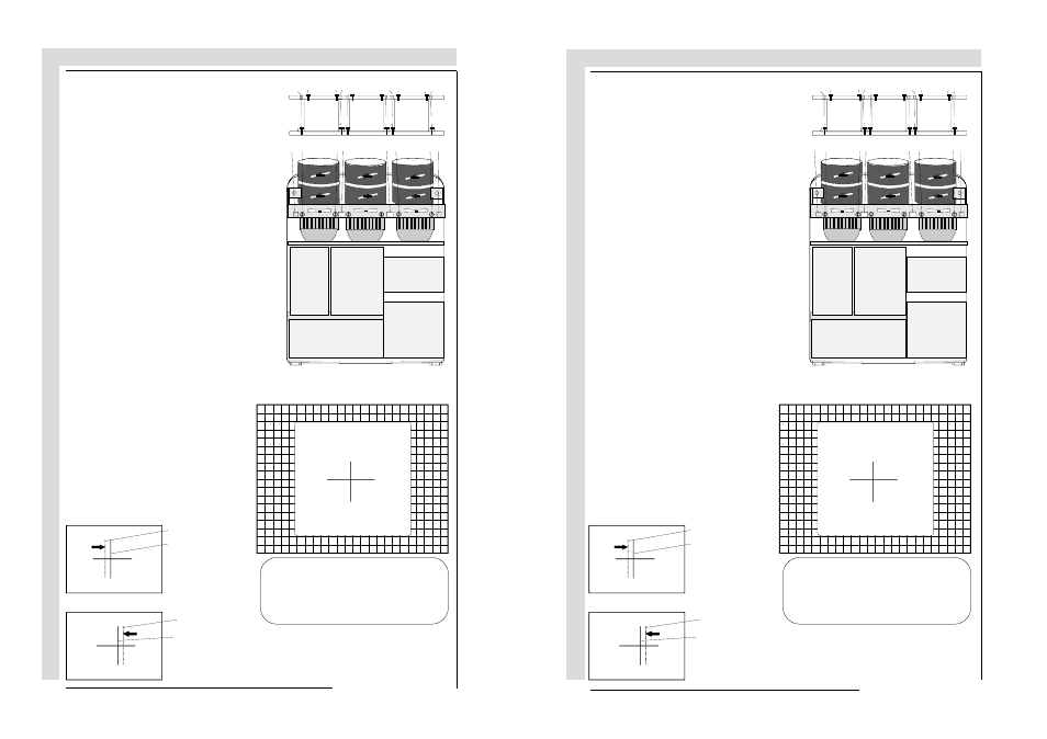
red crosshair
green crosshair
red crosshair
green crosshair
Move the red CRT
to the outside,
away from the
green CRT
Move the red CRT to-
wards the green CRT
Screws A, B, C and D (M4) : upper
fixation latch. nutdriver 7mm.
Screw A', B', C' and D' (M4) : lower
fixation latch. nutdriver 7mm.
These screws fasten the cooling
house of the red tube.
Pivot the red CRT until the center of the
red image coincides with the center of
the green image. If the angle of the red
CRT is corrected, tighten the four
bolts.
ENTER continues to blue and green
crosshairs.
EXIT will return to CRT projection angle
adjustment.
Loosen the four hexagon screws C, C',
D and D', upper and lower fixation latch.
$
%
&
'
$
%
&
'
$ $
%
&
%
&
'
'
CRT
PROJECTION ANGLE
ADJUSTMENT
Align crosshairs
red crosshair
green crosshair
red crosshair
green crosshair
Move the red CRT
to the outside,
away from the
green CRT
Move the red CRT to-
wards the green CRT
Screws A, B, C and D (M4) : upper
fixation latch. nutdriver 7mm.
Screw A', B', C' and D' (M4) : lower
fixation latch. nutdriver 7mm.
These screws fasten the cooling
house of the red tube.
Pivot the red CRT until the center of the
red image coincides with the center of
the green image. If the angle of the red
CRT is corrected, tighten the four
bolts.
ENTER continues to blue and green
crosshairs.
EXIT will return to CRT projection angle
adjustment.
Loosen the four hexagon screws C, C',
D and D', upper and lower fixation latch.
$
%
&
'
$
%
&
'
$ $
%
&
%
&
'
'
CRT
PROJECTION ANGLE
ADJUSTMENT
Align crosshairs