Mg-30 pump — initial start-up/operation – Multiquip MG30M2D User Manual
Page 41
MAYCO MG-30 PUMP — OPERATION AND PARTS MANUAL — REV. #3 (09/15/11) — PAGE 41
MG-30 PUMP — INITIAL START-UP/OPERATION
Engine Status LED's Definitions.
■ "
Happy Face
" status LED. This LED when lit indicates that
the engine and associated components are functioning
correctly.
■ "
Battery
" status LED. This LED when lit indicates that the
battery charging system is not working correctly. If this LED
remains ON, stop the engine and correct the problem.
■ "
Oil Pressure
" status LED. This LED when lit indicates that
the Oil pressure is low. If this LED remains ON, stop the engine
and correct the problem.
■ "
Water Temperature
" status LED. This LED when lit indicates
that the Water temperature is too high. If this LED remains
ON, stop the engine and correct the problem.
■ "
Air Filter
" status LED. This LED when lit indicates that the air
filter is dirty and is not functioning correctly. If this LED remains
ON, stop the engine and correct the problem.
7.
Let engine run at idling speed for approximately 5 minutes.
8.
Lubricate the pump head and hose by filling the hopper
half full with clean water.
The purpose of lubricating the
pump head and hose, is that dry surfaces remove water,
which causes the hose to pack.
NOTE
If hoses have not been thoroughly
cleaned out, it is suggested that
they be cleaned now to remove
any accumulation of dried sand
etc. which could cause plugging
of hose when material is pumped
(see
Cleaning Procedure
).
10. Permit water to be pumped out until it reaches a level just
above hopper inlet throat.
11. Grab dump handle on mixer and dump contents of mixing
drum into hopper. DO NOT STOP MACHINE UNTIL
MATERIAL HAS REACHED END OF HOSE -
OTHERWISE THIS MAY CAUSE SEPARATION OF
MATERIAL, WHICH COULD CLOG UP PUMP AND
HOSE.
12. If the pump is allowed to suck air at any time, an air block
can develop and the machine will not pump. The air block
can be relieved by opening the pressure release valve
until material flows from the valve.
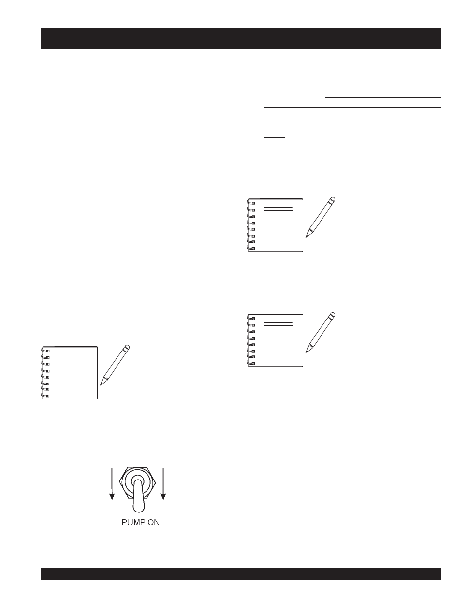
9.
Place the pump control switch (Figure 40) on the control
panel in the
down
position (pumping).
Figure 40. Pumping Control Switch
Down Position (Pumping)
NOTE
Compensator (cam-actuated)
piston will not normally move
when pumping water, as material
back-pressure is required to
return piston to engage cam.
13. Place the pump control switch in the center position to stop
pumping. Install spray nozzle.
14. The plaster and motor pump is now ready to operational.
NOTE
It is suggested that the "
Hose
Connections
" and "
Starting the
Engine" sections be carefully read.
In addition the hose and fittings
should be checked daily prior to
starting the pump. It is also
important that periodic inspections be made during operation.
This preventive maintenance will save hours of un-necessary
maintenance and down time at the job site.