Mg-30 pump — application – Multiquip MG30M2D User Manual
Page 25
MAYCO MG-30 PUMP — OPERATION AND PARTS MANUAL — REV. #3 (09/15/11) — PAGE 25
NOTE
NEVER place the MG-30 into
operation without a safety relief
pressure valve with a manual
release control installed on the
pump discharge.
MG-30 PUMP — APPLICATION
NOTE
ALWAYS
point the brass cap on the
safety valve
downward
. This will
prevent the ball from striking
someone and possibly causing
injury.
Suggestion:
DO NOT use a 1000 psi cap if your pumping requirement is less
than 750 psi.
Always
use a cap that is rated less than the total
system pressure.
The rubber ball will stay in place until an excessive amount of
pressure occurs that will cause the ball to
blow
out through the
opening (Figure 8) in the brass cap and release the pressure in
the hose or line.
Pressure Relief Valve (Automatic)
Purpose
To provide the capability that will
automatically
release the
pressure in a material hose or line whenever the flow of material
is restricted for any reason, causing unsafe pressure to build up
in the hose or line.
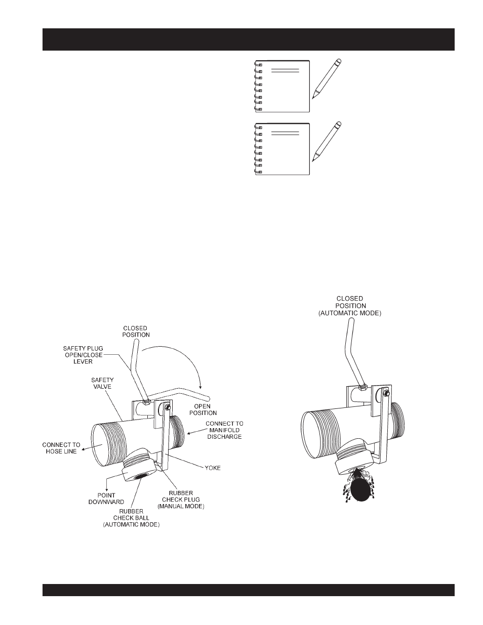
Safety Valve Placement (Automatic)
Place the automatic safety valve at the outlet side of the plaster
pump, ahead of the hose connection. This automatic safety valve
is to be used in conjunction with the manual release mechanism
(
safety relief pressure plug
).
Theory of Operation
Located on the
bottom
of the
safety relief pressure valve
(Figure 7), is a pipe nipple with an opening which is sealed off
with a rubber ball that is held against the opening with a
brass
cap
.
It is the responsibility of the pump operator to ensure that the
delivery hose and line system with all clamps and accessories
have a higher pressure rating than the safety cap being used.
Figure 7. Safety Relief Pressure Valve
(Automatic Mode)
Figure 8. Safety Relief Pressure Valve
(Rubber Check Ball Release)