Figure 5-2. typical electrical schematic – MTS Model 506-62-72 Hydraulic Power Supply User Manual
Page 40
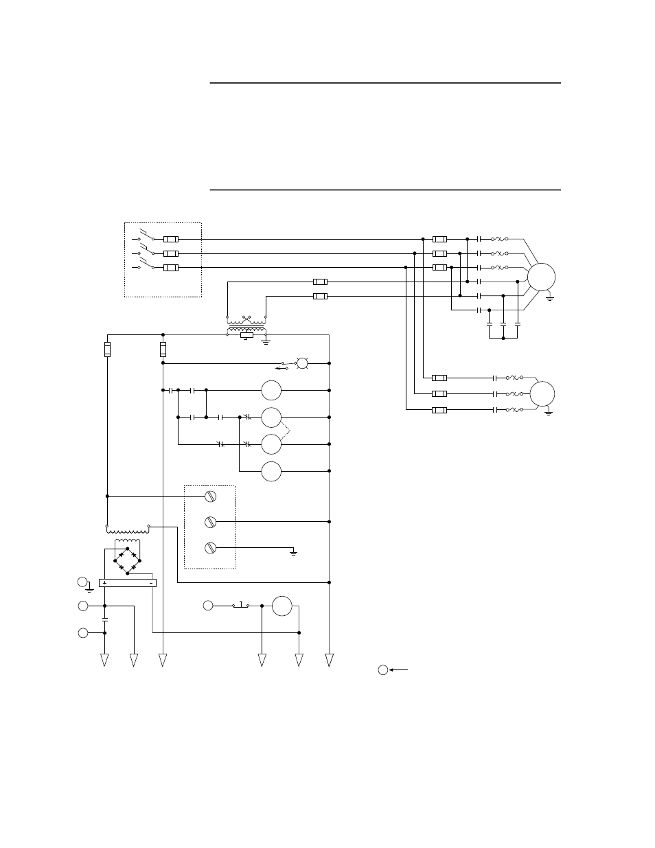
5-6 Theory of Operation
N O T E
Hydraulic power supplies are often customized for
specific applications. Actual wiring may differ from
what is shown in Figure 5-2.
The wiring schematic that is specific to your system can
be found in the product information kit. This kit is
located inside the starter box.
VW-C039A
L
VW-C039A
2MTR
1MTR
R
1HM
1S
3M
2M
E-Stop
2OL
2OL
2OL
1OL
1OL
1OL
2M
2M
2M
3M
3M
3M
8FU
9FU
10FU
1M
1M
1M
2S
2S
2S
power on
motor 1 starter
motor 1 run contactor
motor 1 start contactor
motor 1 hour meter
PLC
master control relay
1FU
2FU
3FU
1LT
4FU
5FU
mechanical
interlock
disconnect switches
supplied by customer
must be grounded
H1
X1
X2
H4
H3 H2
6FU
7FU
1CR
2M
1S
2CR
3M
2CR
1S
115 – 230 Vac
115 Vac neutral
24 Vdc
D
A
CRM
M
24 Vdc
to
outputs
24 Vdc
to
inputs
115 Vac
to
outputs
to
PLC
input 015
to
dc
common
to
ac
common
red
white
green
E
HPS
Spch
Chassis Ground
Balloon with letter indicates MS connector pin
CRM
Figure 5-2. Typical Electrical Schematic
- Series 111 Accumulator (40 pages)
- Series 249G2 Swivels (34 pages)
- Series 201 Actuators (40 pages)
- Series 215 Rotary Actuator (68 pages)
- Series 242 Actuators (40 pages)
- Series 244 Actuators (68 pages)
- Series 247 Actuators (40 pages)
- Series 248 Actuators (46 pages)
- 709 Alignment System (158 pages)
- Series 609 Alignment Fixture (70 pages)
- 494 Controller Hardware FT 40 (344 pages)
- ReNew Technical Reference (50 pages)
- DCPD Measurement System (46 pages)
- Bionix EnviroBath (40 pages)
- FGW900 High-temperature Furnace (38 pages)
- Model 409.83 Temperature Controller (40 pages)
- Series 651 Environmental Chambers (30 pages)
- Series 653 High-Temperature Furnaces (38 pages)
- Series 658 Environmental Chamber (24 pages)
- Series FEC Environmental Chamber (48 pages)
- Model 685.53 Grip Control Module (24 pages)
- Series 685 Hydraulic Grip Supply (48 pages)
- Bend Fixture-10 kN (2 pages)
- Grip-Manual Bend Fixture-100 kN (2 pages)
- Grip-Manual Bollard-2 kN (2 pages)
- Grip-Manual Bollard-500 N (2 pages)
- Compression Platen-100 kN-100mm (2 pages)
- Compression Platen-100 kN-150mm (2 pages)
- Compression Platen-100 kN-200mm (2 pages)
- Compression Platen-20 kN (2 pages)
- Compression Platen-20 kN-100mm (2 pages)
- Compression Platen-20 kN-200mm (2 pages)
- Compression Platen-20 kN-SST (2 pages)
- Compression Platen-500 N FYC502A (2 pages)
- Compression Platen-500 N FYB502A (2 pages)
- Compression Platen-500 N-50mm (2 pages)
- Grip-Pneumatic Vise-Style-1 kN (2 pages)
- Pneumatic Bollard-500 N (2 pages)
- Scissor-Style-2 kN (2 pages)
- Scissor-Style-5 kN (2 pages)
- Screw-Style-5 kN (2 pages)
- Screw-Style-5 kN-SST (2 pages)
- Bend Fixture-1000 kN (2 pages)
- Bend Fixture-300 kN (2 pages)
- Bolt Grips (32 pages)