Section 5 theory of operation, 1 hydraulic operation, Figure 5-1. hydraulic block diagram – MTS Model 506-62-72 Hydraulic Power Supply User Manual
Page 35
Theory of Operation 5-1
Section 5
Theory of Operation
This section describes the hydraulic and electrical operation of Model
506.62/.72 Hydraulic Power Supply (HPS).
5.1
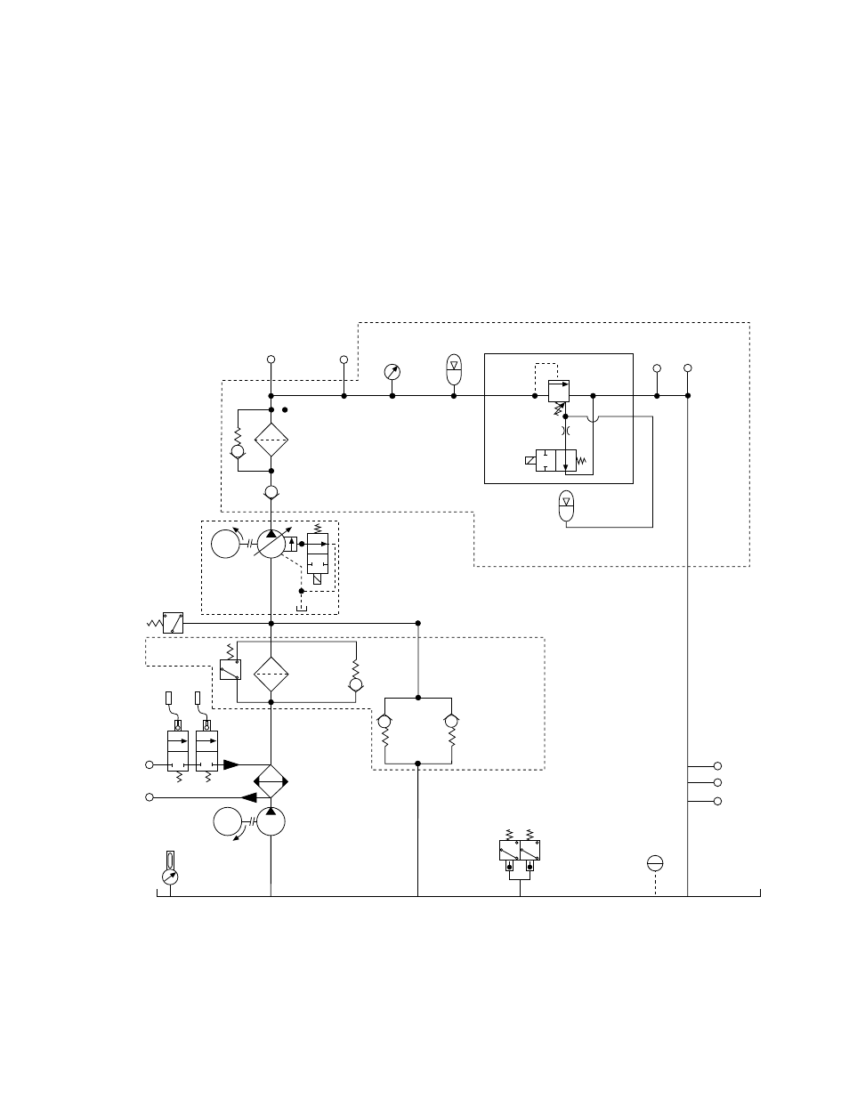
Hydraulic Operation
The figure below shows a block diagram of the HPS hydraulic operation.
High-Pressure
Filter
10-micron
Low-Inlet
Pressure
Switch
Filter
Bypass
Pressure
-20 JIC
Back-up
Relief Valve
Fluid-Level and
Temperature
Gage
TS-C133B
Heat
Exchanger
Output
Pressure
Gage
3500 psi
Pressure
-24 4 Bolt
2 SOL
24 Vdc
Low-Pressure
Fine Filter
3-micron
ER
In
Out
Check
Valve
Main Pump
set
compensator
at 3025 psi
Main Manifold
Assembly
Return
-20 JIC
Return
-24 4 Bolt
Filter Pressure
Switch 2 PS
Supercharge
Relief Valve
preset to crack
at 30 psi
Supercharge and
Filter Manifold
Optional
Water
Control
Valve
Supercharge
Pump
Water-Control
Valve Temperature
Switch
Low-Level
Float
Switch
Over-Temperature
Switch
Pressure
Accumulator
set at 115
°
rising
set at 140
°
rising
-16 JIC
Drain
-12 JIC
-12 JIC
35
psi
1PS
M
M
1 Sol
Bleed-down
Orifice
Slow Turn-on
Accumulator
Figure 5-1. Hydraulic Block Diagram
- Series 111 Accumulator (40 pages)
- Series 249G2 Swivels (34 pages)
- Series 201 Actuators (40 pages)
- Series 215 Rotary Actuator (68 pages)
- Series 242 Actuators (40 pages)
- Series 244 Actuators (68 pages)
- Series 247 Actuators (40 pages)
- Series 248 Actuators (46 pages)
- 709 Alignment System (158 pages)
- Series 609 Alignment Fixture (70 pages)
- 494 Controller Hardware FT 40 (344 pages)
- ReNew Technical Reference (50 pages)
- DCPD Measurement System (46 pages)
- Bionix EnviroBath (40 pages)
- FGW900 High-temperature Furnace (38 pages)
- Model 409.83 Temperature Controller (40 pages)
- Series 651 Environmental Chambers (30 pages)
- Series 653 High-Temperature Furnaces (38 pages)
- Series 658 Environmental Chamber (24 pages)
- Series FEC Environmental Chamber (48 pages)
- Model 685.53 Grip Control Module (24 pages)
- Series 685 Hydraulic Grip Supply (48 pages)
- Bend Fixture-10 kN (2 pages)
- Grip-Manual Bend Fixture-100 kN (2 pages)
- Grip-Manual Bollard-2 kN (2 pages)
- Grip-Manual Bollard-500 N (2 pages)
- Compression Platen-100 kN-100mm (2 pages)
- Compression Platen-100 kN-150mm (2 pages)
- Compression Platen-100 kN-200mm (2 pages)
- Compression Platen-20 kN (2 pages)
- Compression Platen-20 kN-100mm (2 pages)
- Compression Platen-20 kN-200mm (2 pages)
- Compression Platen-20 kN-SST (2 pages)
- Compression Platen-500 N FYC502A (2 pages)
- Compression Platen-500 N FYB502A (2 pages)
- Compression Platen-500 N-50mm (2 pages)
- Grip-Pneumatic Vise-Style-1 kN (2 pages)
- Pneumatic Bollard-500 N (2 pages)
- Scissor-Style-2 kN (2 pages)
- Scissor-Style-5 kN (2 pages)
- Screw-Style-5 kN (2 pages)
- Screw-Style-5 kN-SST (2 pages)
- Bend Fixture-1000 kN (2 pages)
- Bend Fixture-300 kN (2 pages)
- Bolt Grips (32 pages)