2 electrical connections, Figure 4-3. model 506.62/.72 starter assembly – MTS Model 506-62-72 Hydraulic Power Supply User Manual
Page 31
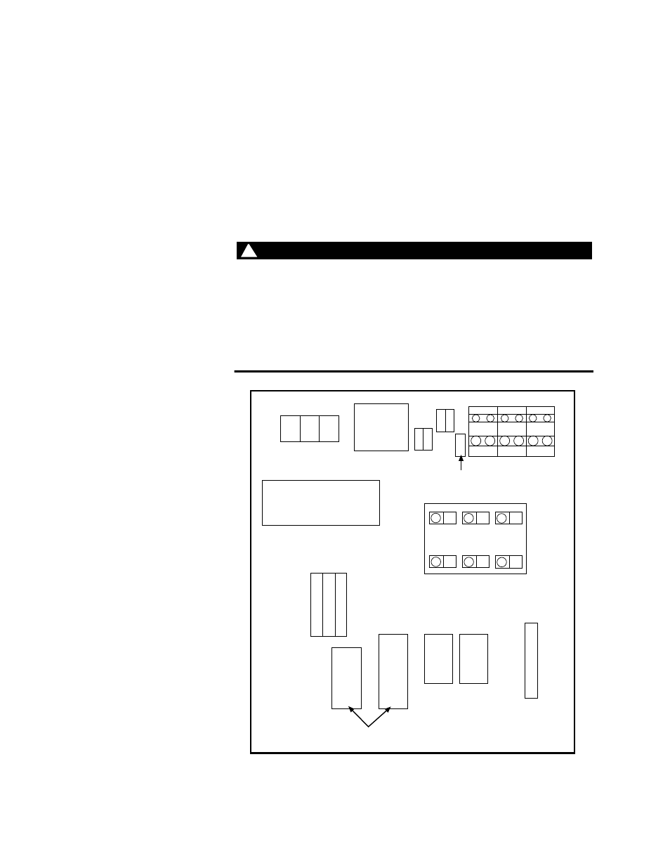
Installation 4-3
4.2
Electrical Connections
The HPS is operated from a three-phase electrical power source. The
operating voltage is labeled on the outside of the starter assembly and
on the pump motor.
Before you begin
Install a fused power disconnect switch (customer supplied). This
switch removes electrical power to the HPS. Local codes dictate the
type of switch to be used. Electrical connections must be made by
qualified personnel and conform to local codes and regulations.
WARNING
!
When the electrical connections have been made, high voltage is
present in the starter assembly when power is on. Do not open the
starter box door with power applied to the HPS.
Touching components with high voltage can cause death.
Remove electrical power at the power disconnect switch before you open
the front starter box door.
Master control
relay
Transformer
Input power
Programmable
logic controller
Earth
ground
SPCH pump fuses
1FU
2FU
3FU
PLC terminal block
6FU
7FU
4FU
5FU
8FU
9FU
10FU
1M
SPCH
starter
2M
Main
pump
starter
3M
1S
Overload
relays
TS-G074
Main pump fuses
Figure 4-3. Model 506.62/.72 Starter Assembly