3 plc service, Table 3-3. 506.62/.72 output indicators, 3 . 3 . 3 plc service – MTS Model 506-62-72 Hydraulic Power Supply User Manual
Page 27
Service 3-15
3 . 3 . 3
PLC Service
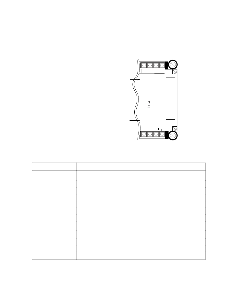
The PLC in the 506.62/.72 HPS starter assembly has output and input
indicators shown in the figure below. These indicators are described in
the following tables.
+
0109
0110
0111
COM
Input indicators
(channel 0)
VW-G073
NC
NC
Output indicators
(channel 1)
24VDC 0.3A
0 1 2 3 4 5 6 7
8 9 10 11
OUTPUT
1CH
0CH
INPUT
0 1 2 3 4 5 6 7
8 9 10 11 12 13 14 15
POWER
RUN
ALARM
ERROR
506.62/.72 Output Indicators
Output Indicator CH1
Description
0
Remote low-level interlock/indication.
1
Remote over-temperature interlock/indication.
2
Remote dirty filter interlock/indication.
3
Remote run indication.
4
Turns on to energize main pump motor start control relay 1CR.
5
Turns on to energize main pump motor run control relay 2CR.
6
Turns on to energize main high-pressure solenoid 1SOL.
7
Turns on to energize water inlet solenoid 2SOL that allows water flow
into the heat exchanger for cooling hydraulic fluid.
8
Turns on to light front panel Low Fluid Level indicator 2LT.
9
Turns on to light front panel Fluid Over Temperature indicator 3LT.
10
Turns on to light front panel Dirty Filter indicator 4LT.
11
Turns on to energize supercharge motor starter 1M