3 starter assembly, Figure 3-3. model 506.62/.72 starter assembly – MTS Model 506-62-72 Hydraulic Power Supply User Manual
Page 25
Service 3-13
3.3
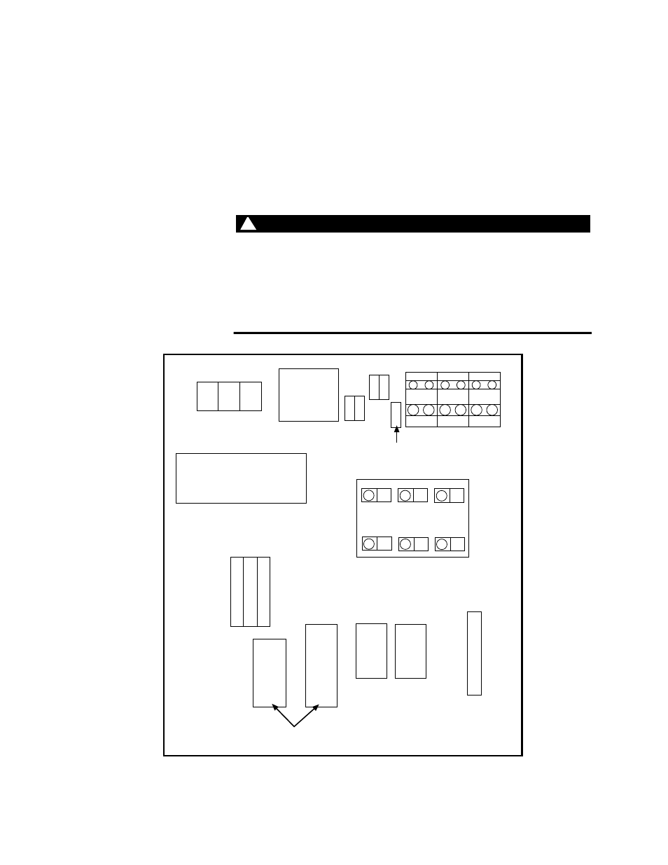
Starter Assembly
The starter assembly (Figure 3-3 shows the location of its components)
is located behind the starter box door. This section provides the
following information:
•
Abnormal HPS Shutdown
•
Fuse Replacement
•
PLC (programmable logic controller) Service
WARNING
WARNING
!
High voltage is present in the starter assembly. Do not open the starter
box door when power is applied to the HPS.
Touching components with high voltage can cause death.
Remove electrical power at the power disconnect switch before you open
the front starter box door.
Master control
relay
Transformer
Input power
Programmable
logic controller
Earth
ground
SPCH pump fuses
1FU
2FU
3FU
PLC terminal block
6FU
7FU
4FU
5FU
8FU
9FU
10FU
1M
SPCH
starter
2M
Main
pump
starter
3M
1S
Overload
relays
TS-G074
Main pump fuses
Figure 3-3. Model 506.62/.72 Starter Assembly
- Series 111 Accumulator (40 pages)
- Series 249G2 Swivels (34 pages)
- Series 201 Actuators (40 pages)
- Series 215 Rotary Actuator (68 pages)
- Series 242 Actuators (40 pages)
- Series 244 Actuators (68 pages)
- Series 247 Actuators (40 pages)
- Series 248 Actuators (46 pages)
- 709 Alignment System (158 pages)
- Series 609 Alignment Fixture (70 pages)
- 494 Controller Hardware FT 40 (344 pages)
- ReNew Technical Reference (50 pages)
- DCPD Measurement System (46 pages)
- Bionix EnviroBath (40 pages)
- FGW900 High-temperature Furnace (38 pages)
- Model 409.83 Temperature Controller (40 pages)
- Series 651 Environmental Chambers (30 pages)
- Series 653 High-Temperature Furnaces (38 pages)
- Series 658 Environmental Chamber (24 pages)
- Series FEC Environmental Chamber (48 pages)
- Model 685.53 Grip Control Module (24 pages)
- Series 685 Hydraulic Grip Supply (48 pages)
- Bend Fixture-10 kN (2 pages)
- Grip-Manual Bend Fixture-100 kN (2 pages)
- Grip-Manual Bollard-2 kN (2 pages)
- Grip-Manual Bollard-500 N (2 pages)
- Compression Platen-100 kN-100mm (2 pages)
- Compression Platen-100 kN-150mm (2 pages)
- Compression Platen-100 kN-200mm (2 pages)
- Compression Platen-20 kN (2 pages)
- Compression Platen-20 kN-100mm (2 pages)
- Compression Platen-20 kN-200mm (2 pages)
- Compression Platen-20 kN-SST (2 pages)
- Compression Platen-500 N FYC502A (2 pages)
- Compression Platen-500 N FYB502A (2 pages)
- Compression Platen-500 N-50mm (2 pages)
- Grip-Pneumatic Vise-Style-1 kN (2 pages)
- Pneumatic Bollard-500 N (2 pages)
- Scissor-Style-2 kN (2 pages)
- Scissor-Style-5 kN (2 pages)
- Screw-Style-5 kN (2 pages)
- Screw-Style-5 kN-SST (2 pages)
- Bend Fixture-1000 kN (2 pages)
- Bend Fixture-300 kN (2 pages)
- Bolt Grips (32 pages)