Installing cables, Installing cables 26, Basic controller connectors – MTS ReNew Technical Reference User Manual
Page 26
ReNew Technical Reference
26
Installation
Installing cables
Exercise care when connecting cables. Ensure that you are using the correct
cables and that all connections are secure. When you are finished, double-check
to ensure that all components are connected properly.
Turn the power off before connecting cables.
Connecting cables with power applied can cause damage to the equipment.
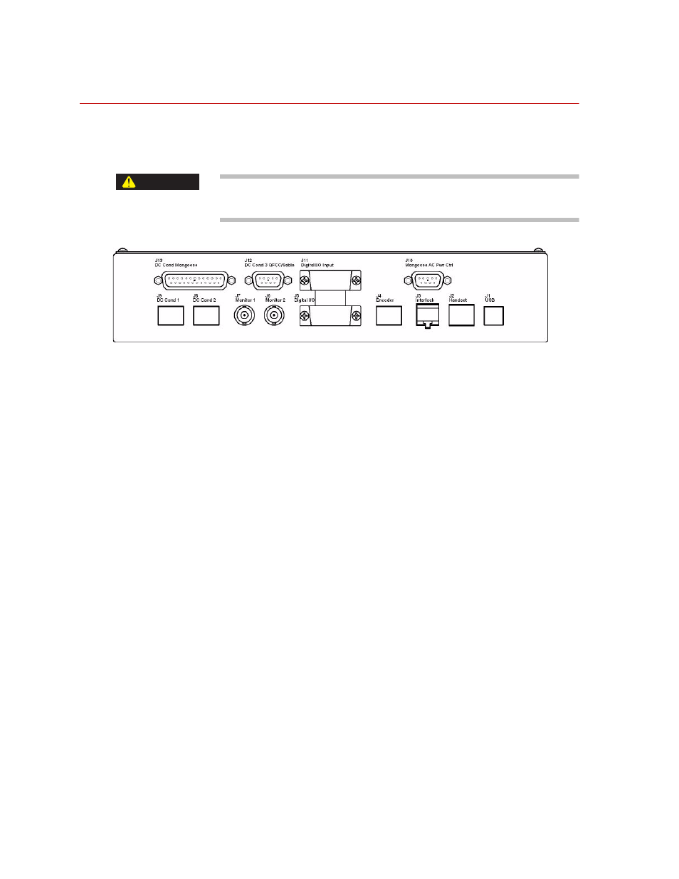
Basic controller connectors
J1—USB. This is the connection to the computer.
J2—Handset. This is intended for a handset.
J3—Interlock. This is intended to connect to a test area enclosure switch that
opens when the door is opened. If not used a jumper plug must be installed.
J4—Encoder. This is intended for an encoder based long stroke extensometer.
J5—Digital I/O. Includes (3) optically isolated inputs, (3) optically isolated
outputs and 12V power. Functions of each digital input or output are intended to
be software selectable. Refer to the TestWorks manual for what signals can be
selected.
J6—Monitor 2. BNC output. Intended to be software selectable analog output
with +/-10V full scale. Refer to the TestWorks manual for what signals can be
selected.
J7—Monitor 1. BNC output. Intended to be software selectable analog output
with +/-10V full scale. Refer to the TestWorks manual for what signals can be
selected.
CAUTION