2 actual value and status signals – Lenze E94AxHE Technology Application Synchronism User Manual
Page 24
9400 Technology applications | Synchronism with mark synchronisation
Parameter setting & configuration
Assignment of the I/O terminals
24
L
EDS94TA10040xxxx EN 1.1 - 10/2008
4.2.2
Actual value and status signals
The following tables contain the Lenze assignment of the analog and digital outputs for
the "Synchronism" technology application.
r
The default signal configuration if required can be easily changed by parameterising
the multiplexer parameters assigned.
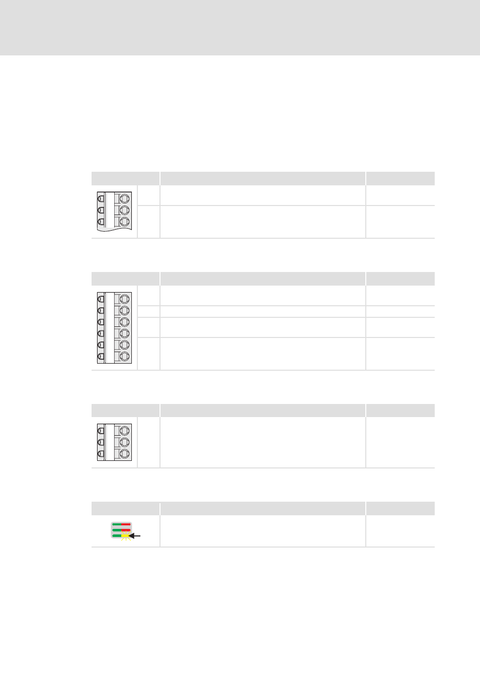
Analog outputs
Digital outputs
State bus
Display elements
Terminal X3
Signal (Lenze setting)
Signal configuration
AO1
Motor speed
• Scaling: ±10 V ≡ motor reference speed (C00011)
C03110/1
AO2
Motor torque (setpoint)
• Scaling: ±10 V ≡ Motor reference torque (C00057/2)
C03110/2
Terminal X4
Signal (Lenze setting)
Signal configuration
DO1
Status "Drive ready"
• DC-bus voltage is available and no error has occurred.
C03100/1
DO2
Status "Electrical shaft enabled"
C03100/2
DO3
Status "Limitation active"
• A setpoint is limited at the moment.
C03100/3
DO4
"Error" status
• If the controller is in the error state, the digital output DO4 is set
to HIGH level.
C03100/4
Terminal X2
Signal (Lenze setting)
Signal configuration
SB
"Application error" status
• The state bus is put in the "error" status.
C03100/5
User LED
Signal (Lenze setting)
Signal configuration
Status "Electrical shaft enabled"
C03100/6
GA
AO1
AO2
GO
24O
DO1
DO2
DO3
DO4
GE
24E
SB