4 speed pot and preset speed control – Lenze MC1000 Series User Manual
Page 41
13435742_EDBM101_v24
37
15.4
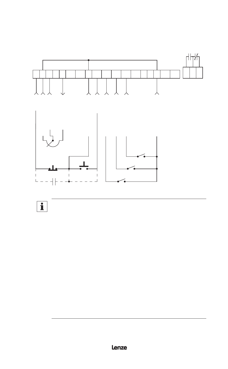
SPEED POT AND PRESET SPEED CONTROL
Shown below is the wiring diagram for a control scheme that utilizes a speed pot and
PRESET SPEEDS for speed control, and either a two-wire or three-wire START/
STOP circuit:
ST
OP
CIR
CUIT C
OMMON
0-10 VDC
INPUT
10 VDC
SUPPL
Y
CIR
CUIT C
OMMON
ST
AR
T
1 2 5A 5B 6 10A
12A
RXA TXB
10B 2
13A 13B 13C 13D 14 15 2
16 17 18
PRESE
T SPEED #3
SPEED POT
(10 K)
PRESE
T SPEED #1
PRESE
T SPEED #2
CIR
CUIT C
OMMON
The TB-2 terminals are internally tied together
NOTE
1. Program the PRESET SPEEDS (Parameters 1-4) to the desired
values.
2. Program TB-13A to select SPEED #1, TB-13B to select SPEED
#2, and TB-13C to select SPEED #3 (refer to Parameters 47,
48, and 49).
3. To select a preset speed, close the appropriate terminal to TB-2.
To select SPEED #4, close any two of the preset speed terminals
to TB-2.
4. Speed pot control can be selected by one of two methods. If
none of the preset speeds are selected (all TB-13 terminals are
open), the drive will default to speed pot control if Parameter
29 - MANUAL is set to 0-10 VDC. The speed pot can also be
selected if one of the TB-13 terminals is programmed to select
0-10 VDC and that terminal is closed to TB-2.
5. If REVERSE rotation is required, TB-13C cannot be used to
select SPEED #3. TB-13C must be programmed to select RUN
REVERSE or START REVERSE, leaving only TB-13A and TB-
13B to select preset speeds.