Lenze MC1000 Series User Manual
Page 38
34
13435742_EDBM101_v24
15
MC1000 CONTROL WIRING DIAGRAMS
15.1
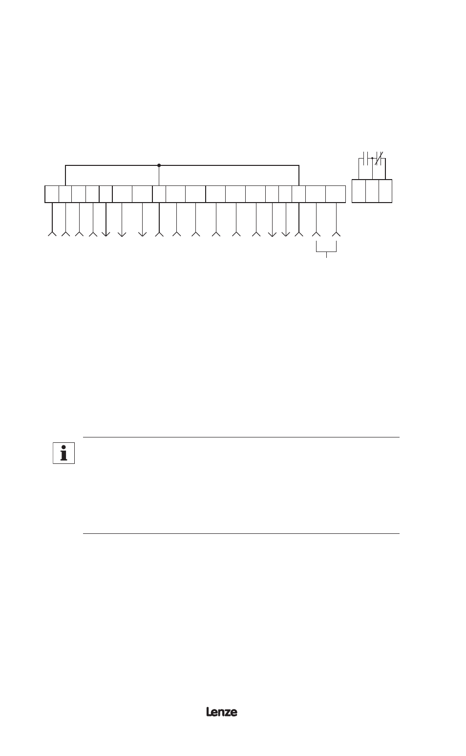
MC1000 TERMINAL STRIP
Shown below is the terminal strip on the main control board, along with a brief
description of the function of each terminal. Wiring shown above the terminal strip
indicates internal wiring on the main control board.
FORM C
RELAY
1 2 5A 5B 6 10A
12A
RXA TXB
10B 2
13A 13B 13C 13D 14 15 2
16 17 18
ST
OP
CIR
CUIT C
OMMON
0-10
VDC SPEED REFERENCE INPUT
10
VDC SUPPL
Y FOR SPEED PO
T
0-10 OR 2-10
VDC OUTPUT
: FREQUENC
Y
0-10 OR 2-10
VDC OUTPUT
: L
O
AD
CIR
CUIT C
OMMON
ST
AR
T
TB
-13A FUNC
TION SELEC
T
TB
-13B FUNC
TION SELEC
T
TB
-13C FUNC
TION SELEC
T
TB
-13D FUNC
TION SELEC
T
OPEN-
COLLEC
TOR OUTPUT
OPEN-
COLLEC
TOR OUTPUT
RS
-485 SERIAL
COMMUNIC
ATIONS
CIR
CUIT C
OMMON
4-20 mA SPEED REFERENCE INPUT
The TB-2 terminals are internally tied together
NOTE
The function of terminals TB-10A, TB-10B, TB-13A, TB-13B, TB-13C,
TB-13D, TB-14, TB-15, TB-16, and TB-18 are dependent on the
programming of certain parameters. In most cases, the name of the
parameter matches the number of the terminal, allowing quick and easy
programming of the terminals to suit the application. The exception is
TB-16 and TB-18, which are governed by Parameter 54 - RELAY.
A complete description of operating the drive in the REMOTE mode can be found
in Section 14.2. The following diagrams provide a quick reference to wire the drive
for the most common configurations.