2 two-wire start/stop control – Lenze MC1000 Series User Manual
Page 39
13435742_EDBM101_v24
35
15.2
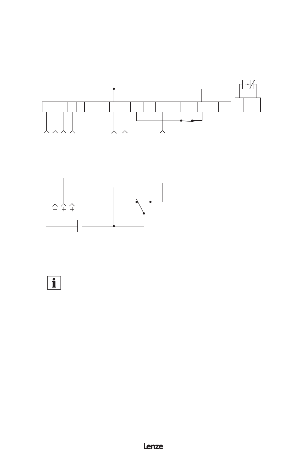
TWO-WIRE START/STOP CONTROL
Shown below is the wiring diagram for a typical two-wire start/stop control scheme,
using one maintained contact (such as that from a PLC) for RUN and STOP
commands. Close the contact to RUN, and open the contact to STOP. Also shown
is the wiring for a 0-10 VDC or 4-20 mA speed reference signal.
ST
OP
CIR
CUIT C
OMMON
0-10 VDC
INPUT
4-20 mA INPUT
CIR
CUIT C
OMMON
ST
AR
T FOR
W
ARD
MAINTAINED
RUN/STOP
CONTACT
1 2 5A 5B 6 10A
12A
RXA TXB
10B 2
13A 13B 13C 13D 14 15 2
16 17 18
ST
AR
T RE
VERSE
0-10 VDC or 4-20 mA
SELECT (see Note 3)
FWD
REV
(see Note 2)
The TB-2 terminals are internally tied together
NOTE
1. Close TB-1 to TB-2 to RUN, and open to STOP.
2. If REVERSE direction is required, ROTATION must be set to
FWD&REV, and TB-13C must be set to START REVERSE (refer
to Parameters: 27 - ROTATION, and 49 - TB-13C).
If REVERSE is not required, jumper TB-2 to TB-12A and
eliminate the FWD/REV switch.
3. Program TB-13A, 13B, or 13C to select the appropriate speed
reference signal that will control the drive speed (refer to
Parameters 47, 48, and 49). When that TB-13 terminal is closed
to TB-2, the drive will respond to the selected speed reference
signal. In the diagram above, TB-13A is programmed to select
either a 0-10 VDC or 4-20 mA signal.
4. If the contact closure is not made between TB-13A and TB-2 to
select a speed reference, the drive will default to MANUAL speed
control, which is determined by Parameter 29 - MANUAL.