Wing to frame installation – Landoll WFPC22-36 Wing Float Pulverizer User Manual
Page 28
2-14
F-701
ASSEMBLY
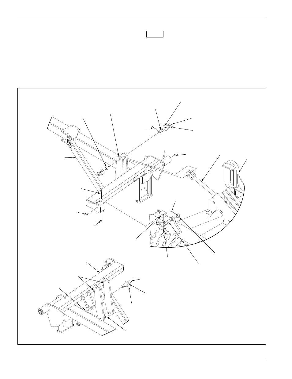
Wing to Frame Installation
Assemble Hitch Ball and Socket Halves into each Wing
Frame, aligning the grease fitting holes.
Assemble Wing Frame onto Center Frame by sliding
Wing Guide Roller into Yoke in the rear and Hitch Ball in
the front. Torque Slotted Nut to 450 Ft-Lbs.
Support Wing Cylinders rod end so that yoke can pass
freely through center frame ramps.
NOTE
While the machine is still supported, bleed the air from
the hydraulic system by cycling the hydraulic circuit
completely a minimum of 5 times. After the circuit is bled
leave wing cylinders extended so that Wing Fold Links
can be installed.
Attach Wing Fold Links to Wing Frame and Hydraulic
Cylinder.
Figure 2-13: Wing to Frame Installation
Wing Frame RH
HHCS, 7/16-14 x 5
Grease Fitting
1/8 PTF x 1-3/4
Spacer, 1.031 x
1.5 x 1.75
Link, Wing Fold
Roll Pin,
5/16 x 2
Spacer, 1.031 x
1.5 x 0.688
Roller Asm
Pin, 1 x 10⁻¹/8
Flat Washer, 1 SAE
Guide
Roller
Grease
Fitting
Cylinder
Guide
Slot
Nut, Lock
7/16-14
Cotter Pin,
1/4 x 2-1/2
Socket Half
w/Tap
Socket Half
Hitch Ball
Slotted Nut,
Heavy 1-1/4-12
Wing Frame RH
Link, Wing Fold
Flat Washer,
1-1/4 SAE
Spacer, 1.38 x
1.66 x 2.75
Pin, 1-1/4 x 7-3/16
Flat Washer, 1-1/4 SAE
Roll Pin, 5/16 x 2