2 analog inputs, 4 electrical connection – JUMO 705020 mTRON T - Analog Input Module, 4-Ch. Operating Manual User Manual
Page 26
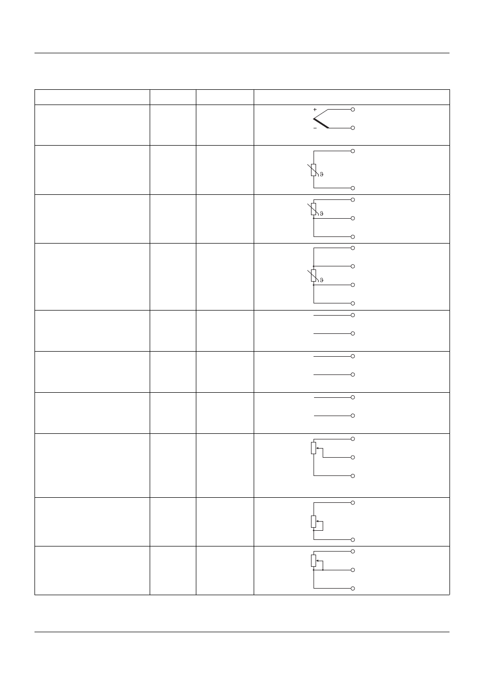
4 Electrical connection
26
4.3.2
Analog inputs
Connection
Input
Terminals
Symbol and terminal designation
Thermocouple
1
2
3
4
2 and 3
6 and 7
10 and 11
14 and 15
2, 6, 10, 14
3, 7, 11, 15
RTD temperature probe
2-wire circuit
1
2
3
4
2 and 4
6 and 8
10 and 12
14 and 16
2, 6, 10, 14
4, 8, 12, 16
RTD temperature probe
3-wire circuit
1
2
3
4
2 to 4
6 to 8
10 to 12
14 to 16
2, 6, 10, 14
3, 7, 11, 15
4, 8, 12, 16
RTD temperature probe
4-wire circuit
1
2
3
4
1 to 4
5 to 8
9 to 12
13 to 16
1, 5, 9, 13
2, 6, 10, 14
3, 7, 11, 15
4, 8, 12, 16
Voltage DC 0(2) to 10 V
1
2
3
4
1 and 2
5 and 6
9 and 10
13 and 14
1, 5, 9, 13
2, 6, 10, 14
Voltage DC 0 to 1 V
1
2
3
4
2 and 3
6 and 7
10 and 11
14 and 15
2, 6, 10, 14
3, 7, 11, 15
Current DC 0(4) to 20 mA
1
2
3
4
3 and 4
7 and 8
11 and 12
15 and 16
3, 7, 11, 15
4, 8, 12, 16
Resistance transmitter
A = Start
E = End
S = Slider
1
2
3
4
2 to 4
6 to 8
10 to 12
14 to 16
2, 6, 10, 14
3, 7, 11, 15
4, 8, 12, 16
Resistance/potentiometer
2-wire circuit
1
2
3
4
2 and 4
6 and 8
10 and 12
14 and 16
2, 6, 10, 14
4, 8, 12, 16
Resistance/potentiometer
3-wire circuit
1
2
3
4
2 to 4
6 to 8
10 to 12
14 to 16
2, 6, 10, 14
3, 7, 11, 15
4, 8, 12, 16
U
+
-
x
U
+
-
x
I
+
-
x
E
S
A
- 7050xx mTRON T - System description (10 pages)
- 705040 mTRON T - Router Module Operating Manual (74 pages)
- 705040 mTRON T - Router Module Installation Instructions (34 pages)
- 705030 mTRON T - Digital Input/Output Module Data Sheet (7 pages)
- 705030 mTRON T - Digital Input/Output Module Operating Manual (50 pages)
- 705021 mTRON T - Analog Input Module, 8-Ch. Data Sheet (8 pages)
- 705021 mTRON T - Analog Input Module, 8-Ch. Operating Manual (56 pages)
- 705020 mTRON T - Analog Input Module, 4-Ch. Data Sheet (10 pages)
- 705015 mTRON T - Relay Module 4-Ch. Data Sheet (5 pages)
- 705015 mTRON T - Relay Module 4-Ch. Operating Manual (44 pages)
- 705010 mTRON T - Multichannel Controller Module Data Sheet (15 pages)
- 705010 mTRON T - Multichannel Controller Module Operating Manual (148 pages)
- 705001 mTRON T - Central Processing Unit Data Sheet (10 pages)
- 705001 mTRON T - Central Processing Unit Operating Manual (152 pages)
- 705060 mTRON T - Multifunction Panel 840 Data Sheet (13 pages)
- 705060 mTRON T - Multifunction Panel 840 Operating Manual (272 pages)
- 709062 TYA 202 - Three-Phase Power Controller Data Sheet (17 pages)
- 709062 TYA 202 - Three-Phase Power Controller Operating Manual (112 pages)
- 709061 TYA 201 - Single-Phase Power Controller Data Sheet (21 pages)
- 709061 TYA 201 - Single-Phase Power Controller Operating Manual (112 pages)
- 709050 IPC IGBT Power Converter Data Sheet (12 pages)
- 709050 IPC IGBT Power Converter IPC 200A Operating Manual (52 pages)
- 709050 IPC IGBT Power Converter IPC 70/100A Operating Manual (52 pages)
- 709050 IPC IGBT Power Converter IPC 70A Operating Manual (48 pages)
- 709040 TYA-110 thyristor power unit Data Sheet (12 pages)
- 709040 TYA-110 thyristor power unit Operating Manual (56 pages)
- 709020 TYA-432 thyristor power switch Data Sheet (5 pages)
- 709010 TYA-432 thyristor power switch Data Sheet (3 pages)
- 706585 LOGOSCREEN fd Data Sheet (21 pages)
- 706585 LOGOSCREEN fd Operating Instructions (108 pages)
- 706585 LOGOSCREEN fd Operating Manual (228 pages)
- 706585 LOGOSCREEN fd Recorder with diecast zinc front Installation Instructions (40 pages)
- 706585 LOGOSCREEN fd Recorder with stainless steel front Installation Instructions (52 pages)
- 706581 LOGOSCREEN nt Data Sheet (18 pages)
- 706581 LOGOSCREEN nt Operating Instructions (108 pages)
- 706581 LOGOSCREEN nt Operating Manual (224 pages)
- 706581 LOGOSCREEN nt Paperless Recorder with TFT display, CompactFlash Installation Instructions (36 pages)
- 706581 LOGOSCREEN nt stainless steel front Installation Instructions (48 pages)
- 706560 LOGOSCREEN es Data Sheet (12 pages)
- 706560 LOGOSCREEN es Operating Instructions (64 pages)
- 706560 LOGOSCREEN es Operating Manual (128 pages)
- 706560 LOGOSCREEN es Installation Instructions (32 pages)
- 706510 LOGOSCREEN 500 cf Data Sheet (10 pages)
- 706510 LOGOSCREEN 500 cf Operating Manual (140 pages)