3 connection diagram, 1 display and connection elements, Connection diagram – JUMO 705020 mTRON T - Analog Input Module, 4-Ch. Operating Manual User Manual
Page 25: 4 electrical connection
25
4 Electrical connection
4.3
Connection diagram
4.3.1
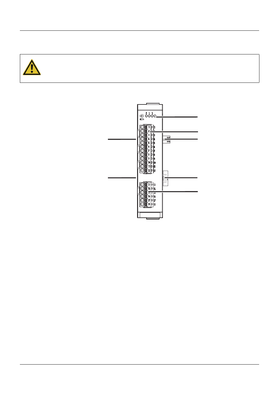
Display and connection elements
CAUTION!
At maximum load, the temperature may exceed 60 °C at the terminals.
As a result the insulation of the cable may be damaged.
The cable must be heat resistant up to at least 80 °C.
(1) Status displays (LED)
P = Voltage supply
S = Status
1 = Digital input
(LED is lit: Active)
(2) Analog input 1 to 3
(3) Voltage supply Out, DC 24 V
(4) Side system bus Out
(5) Analog input 4;
digital input
(6) Side system bus In
(7) Voltage supply In, DC 24 V
(1)
(2)
(3)
(4)
(5)
(7)
(6)
See also other documents in the category JUMO Equipment:
- 7050xx mTRON T - System description (10 pages)
- 705040 mTRON T - Router Module Operating Manual (74 pages)
- 705040 mTRON T - Router Module Installation Instructions (34 pages)
- 705030 mTRON T - Digital Input/Output Module Data Sheet (7 pages)
- 705030 mTRON T - Digital Input/Output Module Operating Manual (50 pages)
- 705021 mTRON T - Analog Input Module, 8-Ch. Data Sheet (8 pages)
- 705021 mTRON T - Analog Input Module, 8-Ch. Operating Manual (56 pages)
- 705020 mTRON T - Analog Input Module, 4-Ch. Data Sheet (10 pages)
- 705015 mTRON T - Relay Module 4-Ch. Data Sheet (5 pages)
- 705015 mTRON T - Relay Module 4-Ch. Operating Manual (44 pages)
- 705010 mTRON T - Multichannel Controller Module Data Sheet (15 pages)
- 705010 mTRON T - Multichannel Controller Module Operating Manual (148 pages)
- 705001 mTRON T - Central Processing Unit Data Sheet (10 pages)
- 705001 mTRON T - Central Processing Unit Operating Manual (152 pages)
- 705060 mTRON T - Multifunction Panel 840 Data Sheet (13 pages)
- 705060 mTRON T - Multifunction Panel 840 Operating Manual (272 pages)
- 709062 TYA 202 - Three-Phase Power Controller Data Sheet (17 pages)
- 709062 TYA 202 - Three-Phase Power Controller Operating Manual (112 pages)
- 709061 TYA 201 - Single-Phase Power Controller Data Sheet (21 pages)
- 709061 TYA 201 - Single-Phase Power Controller Operating Manual (112 pages)
- 709050 IPC IGBT Power Converter Data Sheet (12 pages)
- 709050 IPC IGBT Power Converter IPC 200A Operating Manual (52 pages)
- 709050 IPC IGBT Power Converter IPC 70/100A Operating Manual (52 pages)
- 709050 IPC IGBT Power Converter IPC 70A Operating Manual (48 pages)
- 709040 TYA-110 thyristor power unit Data Sheet (12 pages)
- 709040 TYA-110 thyristor power unit Operating Manual (56 pages)
- 709020 TYA-432 thyristor power switch Data Sheet (5 pages)
- 709010 TYA-432 thyristor power switch Data Sheet (3 pages)
- 706585 LOGOSCREEN fd Data Sheet (21 pages)
- 706585 LOGOSCREEN fd Operating Instructions (108 pages)
- 706585 LOGOSCREEN fd Operating Manual (228 pages)
- 706585 LOGOSCREEN fd Recorder with diecast zinc front Installation Instructions (40 pages)
- 706585 LOGOSCREEN fd Recorder with stainless steel front Installation Instructions (52 pages)
- 706581 LOGOSCREEN nt Data Sheet (18 pages)
- 706581 LOGOSCREEN nt Operating Instructions (108 pages)
- 706581 LOGOSCREEN nt Operating Manual (224 pages)
- 706581 LOGOSCREEN nt Paperless Recorder with TFT display, CompactFlash Installation Instructions (36 pages)
- 706581 LOGOSCREEN nt stainless steel front Installation Instructions (48 pages)
- 706560 LOGOSCREEN es Data Sheet (12 pages)
- 706560 LOGOSCREEN es Operating Instructions (64 pages)
- 706560 LOGOSCREEN es Operating Manual (128 pages)
- 706560 LOGOSCREEN es Installation Instructions (32 pages)
- 706510 LOGOSCREEN 500 cf Data Sheet (10 pages)
- 706510 LOGOSCREEN 500 cf Operating Manual (140 pages)