JULABO LC 6 Programmable Controller User Manual
Page 42
Electrical connections
42
1
2
3
4
5
6
REG+E-PROG
Programmer input / temperature recorder output (31)
Analog inputs / outputs see page 35
Pin
Signal
1 Voltage output
Channel 1
0 ... 10 V
2 Voltage output
Channel 2
0 ... 10 V
3 GND for outputs
0 V
4 Programmer input
EPROG
0 to 10 V / 0 to 20 mA
5 Current output
Channel 3
0 to 20 mA / 4 to 20 mA
6 GND for Progammer
0 V
1
3
2
4
5
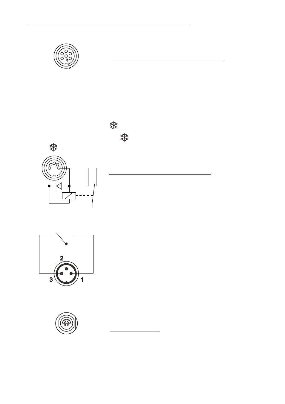
Control output (32)
The
connector may be used for control of JULABO
refrigerated programmable controllers or as output for alarm
messages.
Pin assignment:
Pin
Signal
1
+24 V (I max. current 25 mA)
2
0 V
3
Alarm relay
4
Reserved - do not use!
5 Cooling
pulse
Circuit:
Operation
= relay powered
Alarm
= relay not powered
ALARM
Alarm output (34)
(for external alarm signal)
This potential-free change-over contact is activated in case of
an alarm when pins 2 and 3 are connected.
Switching capacity
max. 30 W / 40 VA
Switching voltage
max. 125 V
/
Switching current
max. 1 A
4
1
3
2
SF
INT
EXT
Socket for temperature sensors (19, 20, 21)
Pin assignment:
Pin
Signal
1
Current+
2
Voltage+
3
Voltage-
4
Current-
- AWC100 Compact Recirculating Cooler (15 pages)
- CF30 Cryo-Compact Circulators (35 pages)
- CF31 Cryo-Compact Circulators (76 pages)
- ED Heating Immersion Circulator (23 pages)
- ED-5A/B Bath Circulators (24 pages)
- ED-5A Open Bath Circulators (24 pages)
- EH Heating Immersion Circulator (27 pages)
- EH-5 Open Bath Circulator (28 pages)
- F250 Recirculating Cooler (35 pages)
- F12-ED Refrigerated / Heating Circulator (26 pages)
- F12-EH Refrigerated and Heating Circulators (32 pages)
- F12-MA Refrigerated and Heating Circulators (65 pages)
- F38-ME Beer Forcing Test Refrigerated/Heating Circulating Bath (69 pages)
- F38-EH Refrigerated and Heating Circulators (30 pages)
- F25-ME Refrigerated and Heating Circulators (66 pages)
- F25-HE Refrigerated and Heating Circulators (86 pages)
- F34-ED Refrigerated / Heating Circulator (25 pages)
- F25-HL Refrigerated Circulators (94 pages)
- FL7006 Recirculating Coolers (34 pages)
- FL2503 Recirculating Coolers (36 pages)
- FL20006 Recirculating Coolers (32 pages)
- FL1201 Recirculating Coolers (33 pages)
- FL300 Recirculating Coolers (48 pages)
- FK30-SL Calibration Baths (88 pages)
- FT200 Immersion Coolers (20 pages)
- FC600_600S Recirculating coolers (37 pages)
- FC1200S Recirculating cooler (45 pages)
- F81-HL Ultra-Low Refrigerated Circulator (93 pages)
- F70-ME Ultra-Low Refrigerated Circulators (64 pages)
- FP52-SL Ultra-Low Refrigerated Circulators (103 pages)
- FP51-SL Ultra-Low Refrigerated Circulators (90 pages)
- FP45-HE Refrigerated and Heating Circulators (79 pages)
- HL-4 Heating Circulators (89 pages)
- HE-4 Heating Circulators (78 pages)
- F81-HL Ultra-Low Refrigerated Circulators (93 pages)
- FT402 Immersion Coolers (24 pages)
- ME-4 Heating Circulators (62 pages)
- ME-31A Visco-Baths (62 pages)
- ME Heating Immersion Circulator (61 pages)
- MB-17 Open Heating Bath Circulators (52 pages)
- MB Heating Immersion Circulator (48 pages)
- Magnum 91 Temperature System (77 pages)
- MA-4 Heating Circulators (51 pages)
- MA Heating Immersion Circulator (50 pages)
- LH 47 Highly Dynamic Temperature Control Systems (76 pages)