JULABO LC 6 Programmable Controller User Manual
Page 16
Operating procedures
16
5.3.
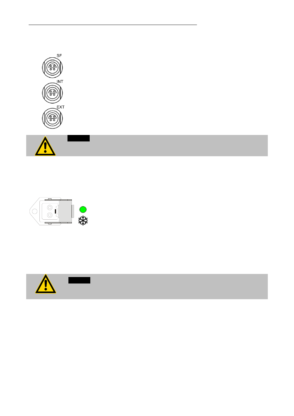
Connecting the temperature sensors
To avoid error message and safety shutdown (see page 40),
attach sensors “SF” and “INT” before switching the instrument
ON.
Attach the working sensor to socket labeled “INT” and the
safety sensor to socket labeled “SF”.
Sensor calibration:
When the controller is first placed into operation or whenever a
sensor is replaced, a working sensor calibration must be
carried out (ATC - see page 39).
Caution:
Place both sensors into the bath medium and securely fix the sensors.
5.4.
Controlling an intermittent cooling water supply
The control output (35) is intended for the attachment of a
solenoid valve (230 V or 115 V - max. 1.25 A) which can be
used to control the flow of a liquid coolant. The flow of a
coolant is indicated by the illumination of a green indication
light on the control panel of LC6.
The solenoid valve is designed to be attached to the coolant
supply line.
Order-No.
Description
8 980 703-3
Solenoid valve (230 V)
8 980 703-2
Solenoid valve (115 V)
Caution:
Securely attach all tubing to prevent slipping.
- AWC100 Compact Recirculating Cooler (15 pages)
- CF30 Cryo-Compact Circulators (35 pages)
- CF31 Cryo-Compact Circulators (76 pages)
- ED Heating Immersion Circulator (23 pages)
- ED-5A/B Bath Circulators (24 pages)
- ED-5A Open Bath Circulators (24 pages)
- EH Heating Immersion Circulator (27 pages)
- EH-5 Open Bath Circulator (28 pages)
- F250 Recirculating Cooler (35 pages)
- F12-ED Refrigerated / Heating Circulator (26 pages)
- F12-EH Refrigerated and Heating Circulators (32 pages)
- F12-MA Refrigerated and Heating Circulators (65 pages)
- F38-ME Beer Forcing Test Refrigerated/Heating Circulating Bath (69 pages)
- F38-EH Refrigerated and Heating Circulators (30 pages)
- F25-ME Refrigerated and Heating Circulators (66 pages)
- F25-HE Refrigerated and Heating Circulators (86 pages)
- F34-ED Refrigerated / Heating Circulator (25 pages)
- F25-HL Refrigerated Circulators (94 pages)
- FL7006 Recirculating Coolers (34 pages)
- FL2503 Recirculating Coolers (36 pages)
- FL20006 Recirculating Coolers (32 pages)
- FL1201 Recirculating Coolers (33 pages)
- FL300 Recirculating Coolers (48 pages)
- FK30-SL Calibration Baths (88 pages)
- FT200 Immersion Coolers (20 pages)
- FC600_600S Recirculating coolers (37 pages)
- FC1200S Recirculating cooler (45 pages)
- F81-HL Ultra-Low Refrigerated Circulator (93 pages)
- F70-ME Ultra-Low Refrigerated Circulators (64 pages)
- FP52-SL Ultra-Low Refrigerated Circulators (103 pages)
- FP51-SL Ultra-Low Refrigerated Circulators (90 pages)
- FP45-HE Refrigerated and Heating Circulators (79 pages)
- HL-4 Heating Circulators (89 pages)
- HE-4 Heating Circulators (78 pages)
- F81-HL Ultra-Low Refrigerated Circulators (93 pages)
- FT402 Immersion Coolers (24 pages)
- ME-4 Heating Circulators (62 pages)
- ME-31A Visco-Baths (62 pages)
- ME Heating Immersion Circulator (61 pages)
- MB-17 Open Heating Bath Circulators (52 pages)
- MB Heating Immersion Circulator (48 pages)
- Magnum 91 Temperature System (77 pages)
- MA-4 Heating Circulators (51 pages)
- MA Heating Immersion Circulator (50 pages)
- LH 47 Highly Dynamic Temperature Control Systems (76 pages)