INFICON BPG400 ATM to Ultra-High Vacuum Gauge User Manual
Page 50
50
tina03e1-b (2004-02) BPG400 v1.om
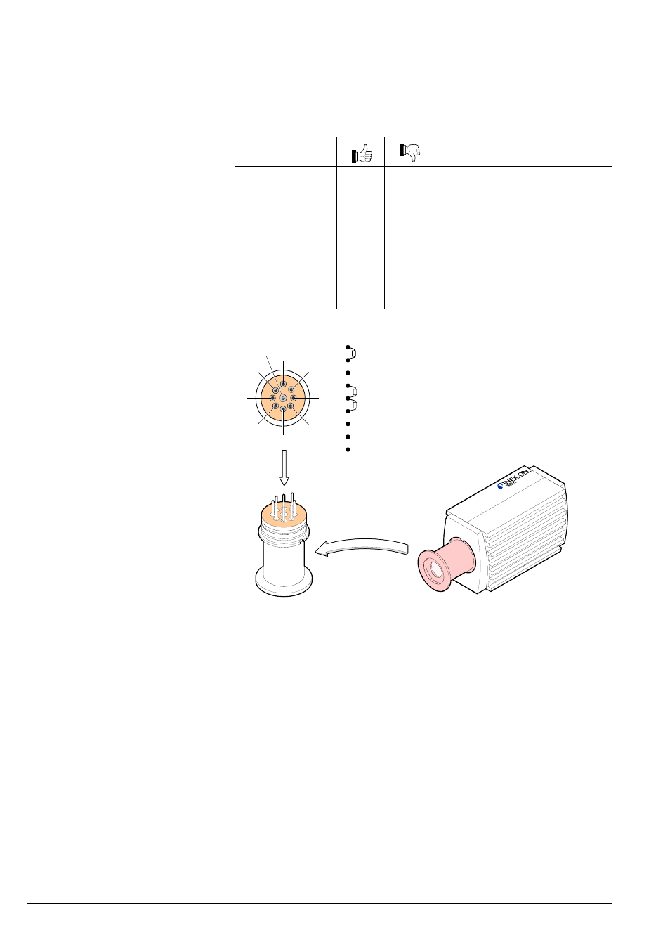
If the cause of a fault is suspected to be in the sensor, the following checks can be
made with an ohmmeter (the vacuum system need not be vented for this purpose).
Separate the sensor from the electronics unit (
→ 14). Using an ohmmeter, make
the following measurements on the contact pins.
Ohmmeter measure-
ment between pins
Possible cause
2 + 4
≈37 Ω
>>37
Ω Pirani element 1 broken
4 + 5
≈37 Ω
>>37
Ω Pirani element 2 broken
6 + 7
≈0.15 Ω >>0.15 Ω Filament of hot cathode broken
4 + 1
∞
<<
∞
Electrode - short circuit to ground
6 + 1
∞
<<
∞
Electrode - short circuit to ground
3 + 1
∞
<<
∞
Electrode - short circuit to ground
9 + 1
∞
<<
∞
Electrode - short circuit to ground
6 + 3
∞
<<
∞
Short circuit between electrodes
9 + 3
∞
<<
∞
Short circuit between electrodes
1
2
3
4
5
6
7
8
9
View on sensor pins
Hot cathode
approx. 0.15 Ohm
Ion collector
Pirani sensor 1
approx. 37 Ohm
Pirani sensor 2
approx. 37 Ohm
6
7
8
2
4
5
3
1
9
Anode
Not connected
GND (connected to sensor housing)
All of the above faults can only be remedied by replacing the sensor (
→ 51).
Error diagnosis of fieldbus gauges can only be performed as described above for
the basic sensor and sensor electronics. Diagnosis of the fieldbus interface can
only be done via the superset bus controller (
→ [1], [2] or 37).
For diagnosis of the BPG400-SD (DeviceNet) gauges, the status lights might pro-
duce some useful information (
→ 35).
Troubleshooting (sensor)
Correction
Troubleshooting on
Fieldbus Gauges
(BPG400-SD, -SP, -SR)