Warning, Sensor cable connection bpg400-sd, -sp, -sr – INFICON BPG400 ATM to Ultra-High Vacuum Gauge User Manual
Page 21
tina03e1-b (2004-02) BPG400 v1.om
21
.
15
8
9
1
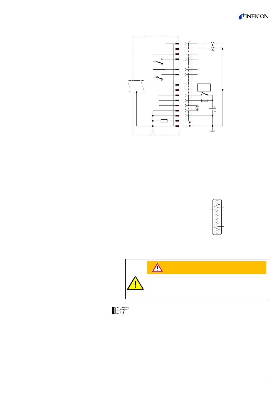
D-Sub, 15 pins
female,
soldering side
Electrical connection
Pin 1 Relay Switching function A, COM contact
Pin 2 Signal output (measuring signal)
0 … +10 V
Pin 3 Threshold value (Setpoint) A
0 … +10 V
Pin 4 Relay Switching function A, N.O. contact
Pin 5 Supply common, GND
Pin 6 Threshold value (Setpoint) B
0 … +10 V
Pin 7 Degas on, active high
+24 V
Pin 8 Supply voltage
+24 V
Pin 9 Relay Switching function B, COM contact
Pin 10 Gauge identification
Pin 11 Relay Switching function B, N.O. contact
Pin 12 Signal common GND
Pin 13 RS232, TxD
Pin 14 RS232, RxD
Pin 15 Shielding, housing GND
SP A
SP B
TxD
RxD
Degas
+U
b
42 k
Ω
BPG400-SD, BPG400-SP, BPG400-SR
Measuring
signal
Threshold value, SP A
Threshold value, SP B
3
6
1
4
9
11
13
14
7
8
2
12
5
15
1.25 AT
24V
Degas
Identification
RS232
10
WARNING
The supply common (Pin 5) and the shielding (Pin 15) must be
connected at the supply unit with protective ground.
Incorrect connection, incorrect polarity or inadmissible supply
voltages can damage the gauge.
For cable lengths up to 5 m (0.34 mm
2
conductor cross-section) the out-
put signal can be measured directly between the positive signal output
(Pin 2) and supply common GND (Pin 5) without loss of accuracy. At
greater cable lengths, differential measurement between signal output
(Pin 2) and signal common (Pin 12) is recommended.
Reassemble the cable connector.
On the other cable end, terminate the cable according to the requirements
of the gauge controller you are using.
Sensor cable connection
BPG400-SD, -SP, -SR