8 profibus interface (bpg400-sp) – INFICON BPG400 ATM to Ultra-High Vacuum Gauge User Manual
Page 36
36
tina03e1-b (2004-02) BPG400 v1.om
This interface allows operation of BPG400-SP with part number
353-505 and
353-506
in connection with other devices that are suited for Profibus operation. The physical
interface and communication firmware of BPG400-SP comply with the Profibus
standard (
→ [7], [5].
Two adjustable switching functions are integrated in the BPG400-SP. The corre-
sponding relay contacts are available at the sensor cable connector (
→ 8, 21,
44).
The basic sensor and sensor electronics of all BPG400 gauges are identical.
Caution
Caution: data transmission errors
If the gauge is operated via RS232C interface and Profibus interface at
the same time, data transmission errors may occur.
The gauge must not be operated via RS232C interface and Profibus
interface at the same time.
Via this interface, the following and further data are exchanged in the standardized
Profibus protocol (
→ [2]):
• Pressure reading
• Pressure unit (Torr, mbar, Pa)
• Degas function
• Gauge adjustment
• Status and error messages
• Status of the switching functions
As the DeviceNet protocol is highly complex, the parameters and programming of
BPG400-SP are described in detail in the separate Communication Protocol
(
→ [2]).
For operating the gauge via Profibus, prior installation of the BPG400 specific GSD
file is required on the bus master side. This file can be downloaded via internet
(
→ [3]).
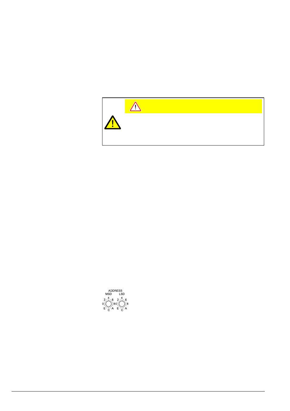
For unambiguous identification of the gauge in a Profibus environment, a node
address is required. The node address setting is made on the gauge.
The node address (0 … 125
dec
) is set in hexadecimal form
(00 … 7D
hex
) via the "ADDRESS", "MSD", and "LSD" switches.
The node address is polled by the firmware when the gauge is
switched on. If the setting deviates from the stored value, the
new value is taken over into the NVRAM. If a value >7D
hex
(>125
dec
) is entered, the node address setting currently stored in
the device remains valid but it can now be defined via Profibus
("Set slave Address",
→ [2]).
The gauge is connected to Profibus via the 9-pin Profibus connector (
→ 23).
4.8 Profibus Interface
(BPG400-SP)
4.8.1 Description of the
Functions
4.8.2 Operating Parameters
4.8.2.1 Operating Software
4.8.2.2 Node Address Setting
Electrical connections