INFICON BPG400 ATM to Ultra-High Vacuum Gauge User Manual
Page 20
20
tina03e1-b (2004-02) BPG400 v1.om
For reasons of compatibility, the expression "sensor cable" is used for all
BPG400 versions in this document, although the pressure reading of the
gauges with fieldbus interface (BPG400-SD, BPG400-SP or
BPG400-SR) is normally transmitted via DeviceNet, Profibus or RS485.
The sensor cable is required for supplying all BPG400 types with power.
In connection with the gauges with fieldbus interface (BPG400-SD,
BPG400-SP and BPG400-SR), it also permits access to the relay con-
tacts of the switching functions (
→ 21, 44).
The application and length of the sensor cable have to be considered when deter-
mining the number and cross sections of the conductors (
→ 9).
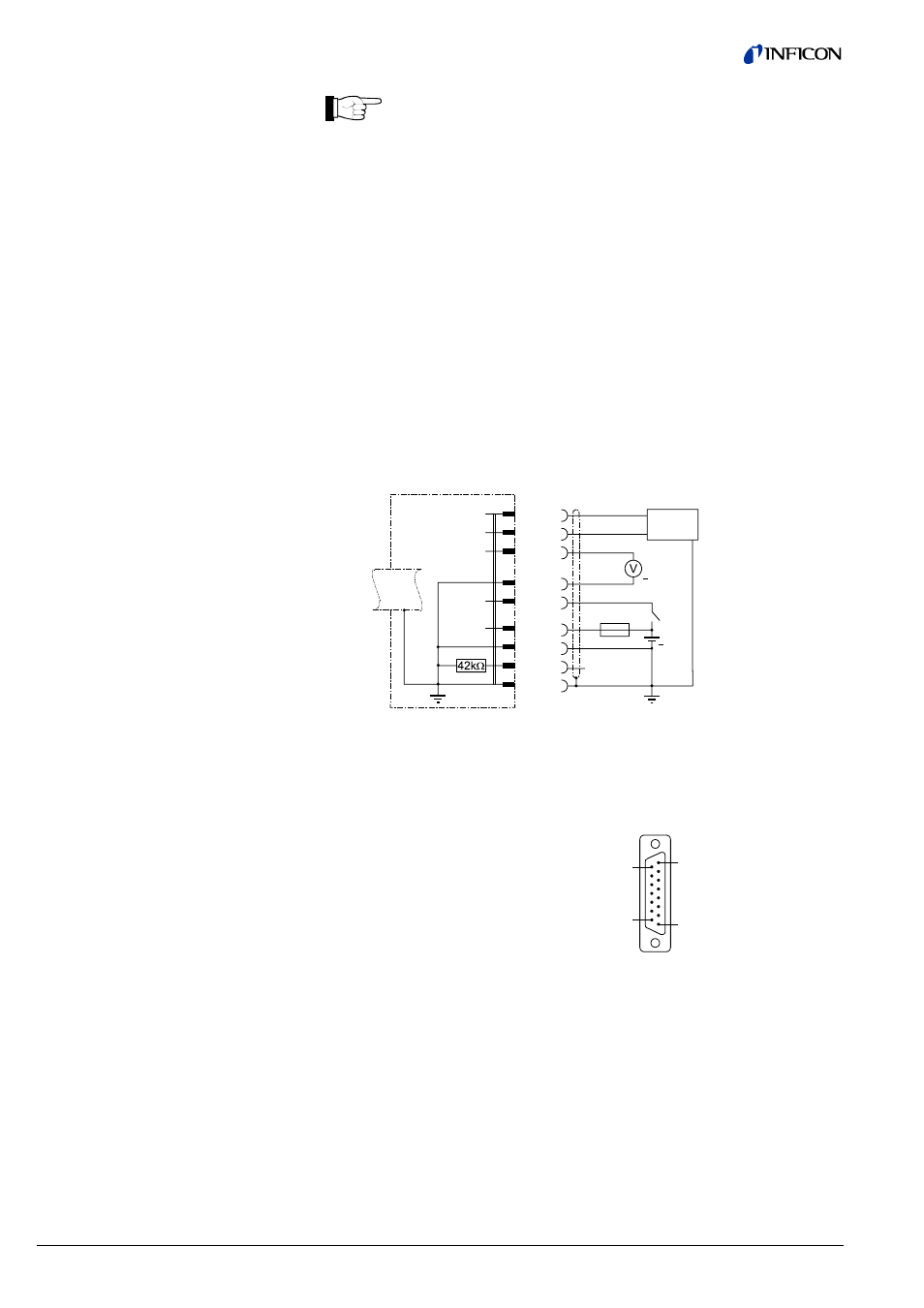
Open the cable connector (D-Sub, 15 pins, female).
Prepare the cable and solder/crimp it to the connector as indicated in the
diagram of the gauge used:
Electrical connection
Pin 2 Signal output (measuring signal)
Pin 5 Supply common, GND
Pin 7 Degas on, active high
Pin 8 Supply
Pin 10 Gauge identification
Pin 12 Signal common, GND
Pin 13 RS232C, TxD
Pin 14 RS232C, RxD
Pin 15 Shielding, housing, GND
8
9
1
15
+24 VDC
+24 VDC
Pins 1, 3, 4, 6, 9 and 11 are
not connected internally.
0 … +10 V
D-Sub, 15 pins
female,
soldering side
TxD
BPG400
RxD
Measuring
signal
Degas
+Ub
13
14
2
12
7
8
5
15
+
1.25AT
Identification
10
RS232C
+
24 V
3.2.2.1 Making an Individual
Sensor Cable
Cable type
Procedure
Sensor cable connection
BPG400