INFICON BPG400 ATM to Ultra-High Vacuum Gauge User Manual
Page 25
tina03e1-b (2004-02) BPG400 v1.om
25
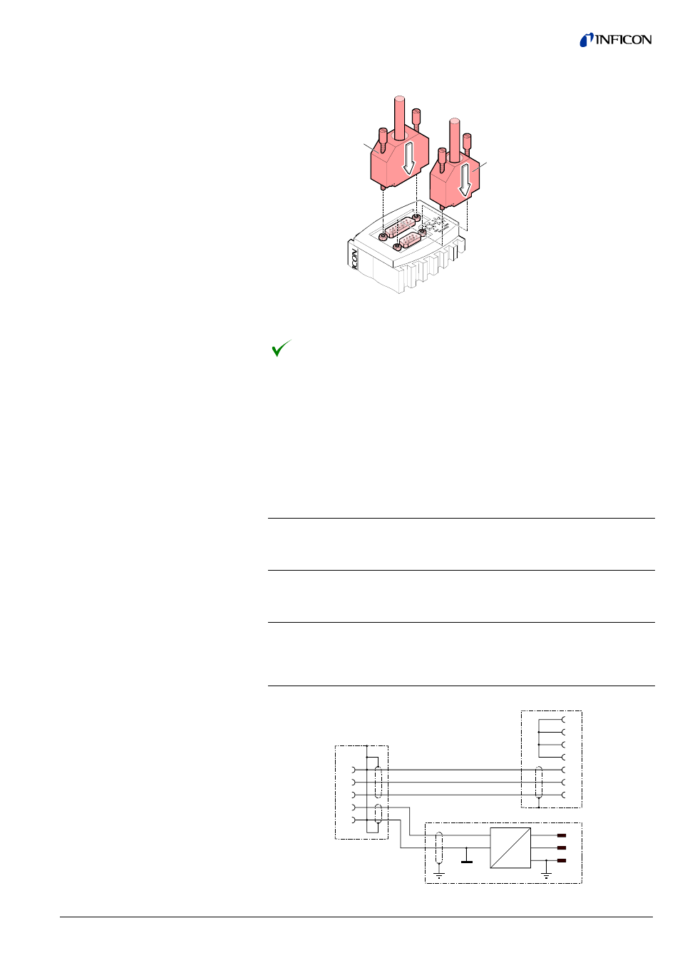
Plug the RS485 (and sensor) cable connector into the gauge.
Sensor cable
RS485 cable
Lock the RS485 (and sensor) cable connector.
The gauge can now be operated via RS485 interface (
→ 37).
The optional 24 V power supply (
→ 52) allows RS232C operation of the BPG400
gauge with any suitable instrument or control device (e.g. PC).
The instrument or control device needs to be equipped with a software that sup-
ports the RS232C protocol of the gauge (
→ 31).
Mains connection
Mains voltage
90 … 250 VAC 50 … 60 Hz
Mains cable
1.8 meter (Schuko DIN and U.S. con-
nectors)
Output (operating voltage of gauge)
Voltage
21 … 27 VDC, set to 24 VDC
Current
Max. 1.5 A
Gauge connection
Connector
D-Sub, 15 pins, female
24 V cable
5 m, black
Connection of the instrument or control
device
RS232C connection
D-Sub, 9 pins, female
Cable
5 m, black, 3 conductors, shielded
13
14
8
15
5
2
3
5
4
6
7
8
N
PE
L
DC
AC
GND
+24 V
PE
BPG400
D-Sub, 15 pins
RS232C
D-Sub, 9 pins
Mains
90 ... 250 VAC
50 ... 60 Hz
3.2.3 Using the Optional Power
Supply (With RS232C
Line)
Technical data
Wiring diagram
- TGF10 Tracer Gas Filler (36 pages)
- Sensistor ILS500 F Leak Detection Filler (90 pages)
- T-Guard Leak Detection Sensor (85 pages)
- T-Guard Leak Detection Sensor Interface description (40 pages)
- Sensistor ISH2000P Hydrogen Leak Detector, Panel Model (51 pages)
- Sensistor ISH2000 HySpeed Hydrogen Leak Detector (54 pages)
- LDS3000 Modular Leak Detector (52 pages)
- LDS3000 Modular Leak Detector Interface description (56 pages)
- BM1000 Bus module (14 pages)
- I/O1000 I/O module (18 pages)
- CU1000 Control unit (24 pages)
- Helium Leak Detector Modul1000 (130 pages)
- Helium Leak Detector Modul1000 Interface description (40 pages)
- UL5000 Dry Helium Leak Detector (108 pages)
- UL5000 Dry Helium Leak Detector Interface description (14 pages)
- UL1000 Fab Dry Helium Leak Detector (119 pages)
- HLD6000 Refrigerant Leak Detector (76 pages)
- HLD6000 Refrigerant Leak Detector Interface Description (40 pages)
- IO1000 I/O module (18 pages)
- Ecotec E3000 Multigas-Sniffer-Leak Detector (92 pages)
- Ecotec E3000 Multigas-Sniffer-Leak Detector Interface description (36 pages)
- Sensistor XRS9012 Hydrogen Leak Detector User Manual (28 pages)
- Sensistor XRS9012 Hydrogen Leak Detector Maintenance manual (14 pages)
- Extrima Ex-certified Hydrogen Leak Detector (62 pages)
- Sensistor ILS500 Leak Detection System (107 pages)
- Sensistor ISH2000 Hydrogen Leak Detector (58 pages)
- Sensistor ISH2000 Hydrogen Leak Detector (108 pages)
- Sensistor Sentrac Hydrogen Leak Detector (86 pages)
- Protec P3000(XL) Helium Leak Detector (132 pages)
- Pilot Plus Vacuum Gauge (2 pages)
- CO Check Carbon Monoxide Meter (2 pages)
- GAS-Mate Combustible Gas Leak Detector (12 pages)
- Whisper Ultrasonic Leak Detector (8 pages)
- Vortex AC Refrigerant Recovery Machine 115V (20 pages)
- Vortex AC Refrigerant Recovery Machine 230V (16 pages)
- Wey-TEK Refrigerant Charging Scale & Optional Charging Module (44 pages)
- Wey-TEK Refrigerant Charging Scale & Optional Charging Module (2 pages)
- D-TEK CO2 Refrigerant Leak Detector (12 pages)
- TEK-Mate Refrigerant Leak Detector (12 pages)
- Compass Refrigerant Leak Detector (12 pages)
- D-TEK Select Refrigerant Leak Detector (12 pages)
- Explorer Portable Gas Chromatograph (369 pages)
- MicroFID II Portable Flame Ionization Detector (89 pages)
- DataFID Portable Flame Ionization Detector for Landfill Emissions Monitoring (91 pages)
- Hydrostik Hydrogen Fuel Cylinder Installation (7 pages)