1 setting the switching functions – INFICON BPG400 ATM to Ultra-High Vacuum Gauge User Manual
Page 44
44
tina03e1-b (2004-02) BPG400 v1.om
The gauges BPG400-SD, BPG400-SP and BPG400-SR have two independent,
manually settable switching functions. Each switching function has a floating nor-
mally open relay contact. The relay contacts are accessible at the sensor cable
connector (
→ 21).
On the BPG400-SR, the change over relay contact of setpoint A is also accessible
at the RS485 interface connector (
→ 24).
The threshold values of switching functions A and B can be set within the pressure
range 1×10
-9
mbar … 100 mbar via potentiometers "SETPOINT A" and
"SETPOINT B".
The Formula applied to calculate the corresponding threshold voltage
U
Threshold
depends on the gauge version used.
For BPG400-SD, -SR :
U
Threshold
= 0.75 × (log p
Setpoint
– c) + 7.75
For BPG400-SP:
U
Threshold
= 0.8129401 × (log p
Setpoint
– c + 9.30102999)
Constant c is pressure unit dependent (
→ Appendix A).
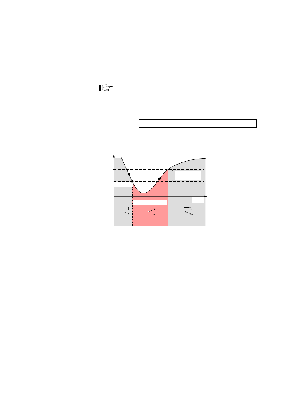
Time t
Mea
sured
value
Off
Off
On
Hysteresis
10% U
Threshold
Switching function
Threshold
U
Measuring signal
(Pressure p)
(Setpoint A, B)
The hysteresis of the switching functions is 10% of the threshold setting.
The threshold values of the two switching functions "SETPOINT A" and
"SETPOINT B" are set locally on the potentiometers of the gauge that are acces-
sible via the openings on one side of the gauge housing.
• Voltmeter
• Ohmmeter or continuity checker
• Screwdriver, max. ø2.5 mm
4.10 Switching Functions
(BPG400-SD, -SP, -SR)
4.10.1 Setting the Switching
Functions
Required tools