INFICON BPG400 ATM to Ultra-High Vacuum Gauge User Manual
Page 24
24
tina03e1-b (2004-02) BPG400 v1.om
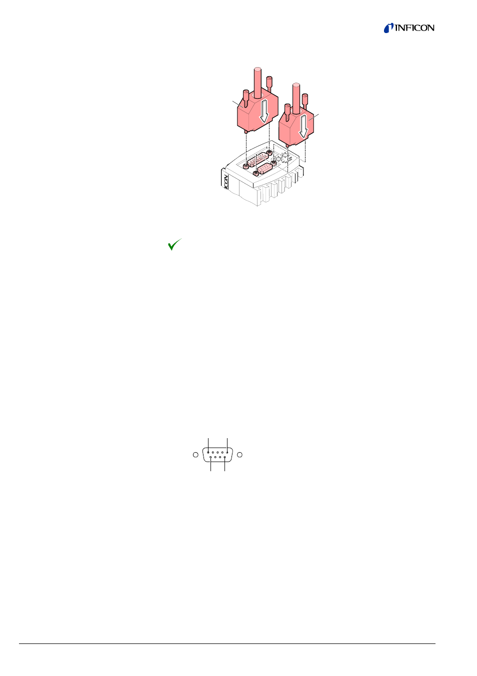
Plug the Profibus (and sensor) cable connector into the gauge.
Sensor cable
Profibus cable
Lock the Profibus (and sensor) cable connector.
The gauge can now be operated via Profibus interface (
→ 36).
For operating BPG400-SR via RS485 bus, a suitable interface cable is required.
If no such cable is available, make one according to the following indications.
For RS485 operation, the following cable data are required:
Cable type:
1 twisted pair, shielded
Coductor cross section:
≥0.22 mm
2
(recommended)
Impedance (Z):
135 … 165
Ω
Capacity between con-
ductors and screen:
≤60 pF/m
Make the RS485 interface cable according to the following indications.
1
5
6
9
D-Sub, 9-pin,
male, soldering side
Pin 1 Setpoint A relay, N.O.
1)
Pin 2 Do not connect
Pin 3 No connection
Pin 4 Do not connect
Pin 5 Setpoint A relay, N.C.
1)
Pin 6 RS485 (-) Input
2)
Pin 7 Setpoint A relay, COM
1)
Pin 8 No connection
Pin 9 RS485 (+) Input
2)
1)
The changeover relay contact available on the RS485 interface con-
nector is galvanically connected to the N.O. contact of the setpoint A re-
lay available on the 25 pin D-sub connector on the BPG400 (
→ 21).
2)
In order to minimize cable reflections, the bus cable must be terminated
at both ends with appropriate termination resistors.
3.2.2.4 Making a RS485
Interface Cable
(BPG400-SR)
Cable type
Procedure