Graff Wall-mount thermostatic showering panel ED1.0, ED2.0 User Manual
Page 9
IOG 2321.00
9
Rev.1 January 2007
A
Wall-mount thermostatic showering panel ED1.0, ED2.0
Panneaux de douche thermostatiques à installer contre le mur ED1.0, ED2.0
Naścienne termostatyczne panele natryskowe ED1.0, ED2.0
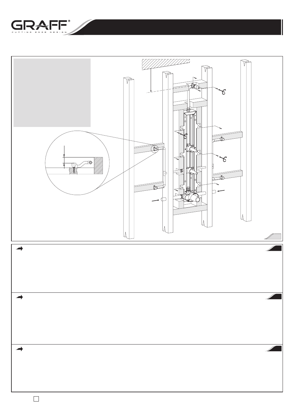
35mm
HOT
Wykończona powierzchnia ściany
Finished wall surface
Surface du mur finie
COLD
MIN. 305mm
Wykończony sufit
Finished ceiling
Plafond fini
Uwaga!
W celu zapewnienia właściwego montażu
zestawu natryskowego wymagana minimalna
odległość od wykończonego sufitu do osi
kolanka zasilającego głowicę natryskową
wynosi 305mm
Caution:
A minimum distance of 305mm from
finished ceiling too the axis of shower head
supply elbow is required to insure proper fit
of trim package.
Note:
Pour assurer un montage correct du jeu de
douche, la distance minimum requise entre
le plafond fini et l’axe du coude d’alimentation
de la douchette est de 305mm
PRÓBA SZCZELNOŚCI POŁĄCZEŃ
Patrz rys. 5
•
Zaślep przewody zasilające dysze boczne do natrysku ciała. Usuń osłonę montażową
(R18) przez obrócenie i ściągnięcie, i upewnij się,
że kolanko zasilające głowicę natryskową jest fabrycznie zaślepione specjalnym korkiem
(R17).
•
Usuń osłony montażowe
(R8) przez obrócenie i ściągnięcie. Ustaw zawór zamykający/sterujący przepływem w pozycji otwartej „ON” – w tym
przypadku obróć przedłużkę wieloklinu zaworu maksymalnie w kierunku przeciwnym do kierunku ruchu wskazówek zegara (w lewo).
•
Odkręć dwa długie wkręty
(R14) przy pomocy śrubokręta płaskiego. Usuń również osłonę montażową zaworu termostatycznego (R13).
•
Włącz zasilanie wodą i sprawdź czy występują przecieki.
•
Wyłącz wodę.
LEAK TEST OF THE CONNECTIONS
See fig. 5
•
Cap the supplies of body sprays. Remove plaster guard
(R18) by turning and pulling and make sure that the shower head supply elbow is factory
plugged by special plug
(R17) included.
•
Remove plaster guards
(R8) by turning and pulling. Position stop/volume control valves at open “ON” position – in this case turn valve spline
elongations max. counterclockwise direction.
•
Unscrew two long screws
(R14) using blade screwdriver. Remove the thermostatic valve plaster guard (R13) too.
•
Turn on the water supplies and check for leaks.
•
Turn off the water.
ESSAI D’ETANCHEITE DES ACCOUPLEMENTS
Voir fig. 5
•
Bouchez les tuyaux d’alimentation des buses latérales de massage en eau. Enlevez le carter de montage
(R18) en le tournant et tirant
et assurez-vous si le coude d’alimentation de la douchette en eau a été bouché préalablement à l’usine par un bouchon spécial
(R17).
•
Enlevez le carter de montage
(R8) en le tournant et tirant. Positionnez la vanne d’arrêt / d’écoulement en position ouverte „ON” – pour l’obtenir,
tournez au maximum la rallonge de la multiclavette dans le sens opposé aux aiguilles d’une montre.
•
Desserrez deux vis longues
(R14) à l’aide d’un tournevis plat. Enlevez aussi le carter de montage de la valve thermostatique (R13).
•
Mettez en marche l’alimentation en eau et assurez-vous s’il n’y a pas des fuites.
•
Coupez l’alimentation en eau.
PL
GB
F
Instrukcja Montażu i Obsługi
n
Instructions for assembly and use
n
Instrucción de Montaje y Servizio
4