Graff Wall-mount thermostatic showering panel ED1.0, ED2.0 User Manual
Page 19
10
0
80
L1
L2
T3
M
T2
T4
T5
R12
IOG 2321.00
19
Rev.1 January 2007
A
Wall-mount thermostatic showering panel ED1.0, ED2.0
Panneaux de douche thermostatiques à installer contre le mur ED1.0, ED2.0
Naścienne termostatyczne panele natryskowe ED1.0, ED2.0
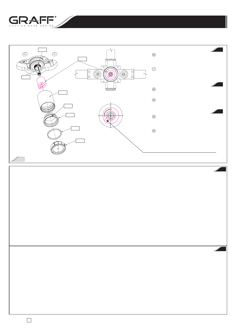
Skoryguj ustawienie pierścienia ograniczającego temperaturę
Correct position of the temperature limiting ring
Corrigez la position de la bague de limitation de la température
PL
KROK 4
Patrz rys. 13
PRZESTROGA! Ryzyko osobistego zranienia lub uszkodzenia mienia. Zestaw natryskowy jest stosunkowo ciężki i jego montaż
wymaga przynajmniej dwóch osób.
•
Włóż tuleje ślizgowe
(T21) do wcześniej przygotowanych pogłębionych otworów cylindrycznych w górnej części nart – stosuj się do
szczegółowej informacji na rys. 13. Wygnij delikatnie górne części nart i włóż głowicę natrysku w taki sposób, aby zgrać osiowo otwór w górnej
części głowicy natrysku z otworami w górnej części „nart”. Trzymaj głowicę natrysku w tym położeniu i z boku „nart” wsuwaj wkręt utrzymujący
(T22) do momentu wystąpienia oporu, a następnie wkręć wkręt utrzymujący przy użyciu śrubokręta płaskiego.
•
Korzystając z pomocy przenieś ostrożnie natrysk do miejsca instalacji i podnieś do położenia naprzeciwko wykończonej ściany. Przemieść zestaw
natryskowy do wykończonej ściany. Umieść ostrożnie zestaw natryskowy na dwóch wystających wkrętach
(R21), a następnie przesuń go powoli
w kierunku dołu, tak aby spoczął na nich. Przymocuj zestaw natryskowy do ściany przy pomocy czterech śrub z łbami gniazdowymi
(R23).
Dokręć te śruby
(R23) przy użyciu dołączonego klucza sześciokątnego.
•
Upewnij się, że zestaw natryskowy jest pewnie przymocowany do wykończonej ściany. Wsuń rozety zaworów
(T16) na tuleje zaworów (T14).
Nasuń rozetę zaworu termostatycznego
(T11) na zespół zaworu termostatycznego oraz umieść ją w poprawnym położeniu.
•
Nałóż uchwyty jak pokazano na rys. 13. W przypadku zaworów zamykających/sterujących przepływem ustaw trzpienie zaworów w pozycji „OFF”.
Obróć trzpienie zaworów
(R6) maksymalnie w kierunku zgodnym z kierunkiem ruchu wskazówek zegara. Przytwierdź uchwyty przy użyciu
zestawu śrub przy pomocy dołączonego klucza sześciokątnego.
•
Wkręć koniec węża
(T19) do gniazda w górnej części głowicy natryskowej (T20).
STEP 4
See fig. 13
CAUTION! Risk of personal injury or property damage. The shower assembly is very heavy and will require at least two
people to safely install.
•
Put the slip bushings
(T21) into earlier prepared counter bores in the top part of the skis - refer to detail on the fig. 13. Bend out slightly the top
parts of the skis and put the shower head in, so that the hole in top part of the showerhead be aligned with the holes in top part of the skis.
Hold the shower head in this position and slide In the holding screw
(T22) from the side of the skis until the resistance is felt, then screw in the
holding screw using the blade screwdriver.
•
With help, carefully carry the shower to the installation location and lift into position against the finished wall. Move the shower assembly
to a finished wall. Position carefully the shower assembly onto the two protruding screws
(R21), then move it slowly downwards so it rests ion
them. Attach the shower assembly to the wall with four socket head screws
(R23). Tighten the screws (R23) using hex key included.
•
Make sure that the shower assembly is securely mounted to a finished wall. Slide the valve plates
(T16) onto the valve sleeves (T14). Slide
the thermostatic valve plate
(T11) onto thermostatic valve assembly and position it correctly.
•
Put on the handles as show on fig. 13. In case of stop/volume control valves, position the valve stems in the OFF position. Turn the stem of valves
(R6) max. in the clockwise direction. Secure the handles with set screws using hex key included.
•
Screw in the ending of the hose
(T19) to the socket in the top part of the shower head (T20).
Wyższa nastawa maksymalnej temperatury
– zdejmij pierścień ograniczający temperaturę
i obróć pierścieniem w kierunku przeciwnym
do kierunku ruchu wskazówek zegara.
Niższa nastawa maksymalnej temperatury
– zdejmij pierścień ograniczający temperaturę
i obróć pierścieniem w kierunku zgodnym
z kierunkiem ruchu wskazówek zegara.
Higher setting of maximum temperature –
remove the temperature limiting ring from
the stem and rotate the ring counterclockwise.
Lower setting of maximum temperature –
remove the temperature limiting ring from
the stem and rotate the ring clockwise.
Pour obtenir la température maximale plus
haute – enlevez la bague de limitation de la
température et tournez la bague dans le sens
opposé aux aiguilles d’une montre.
Pour obtenir la température maximale plus
basse – enlevez la bague de limitation de la
température et tournez la bague dans le sens
des aiguilles d’une montre.
GB
F
PL
GB
Instrukcja Montażu i Obsługi
n
Instructions for assembly and use
n
Instrucción de Montaje y Servizio
12