Graff Wall-mount thermostatic showering panel ED1.0, ED2.0 User Manual
Page 7
IOG 2321.00
7
Rev.1 January 2007
A
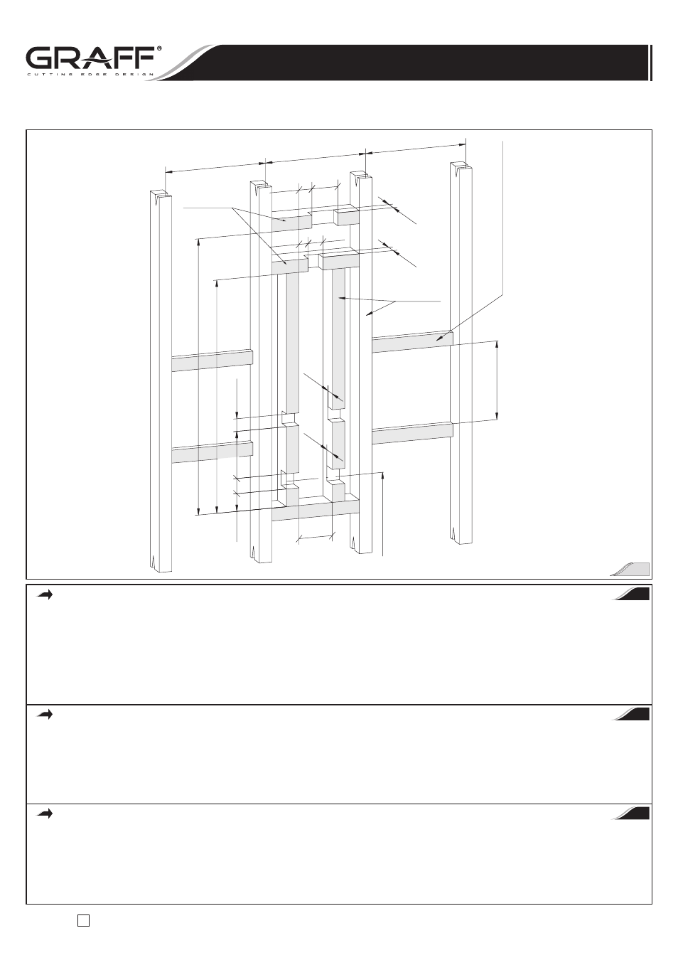
Poziome elementy usztywniające dla k
olanek
doprowadzających wodę do bocznych dysz do masażu
Stringers for body sprays supply elbow
barres horizontales de renforcement pour les coudes
d’alimentation de l’eau aux buses latérales de massage
2"x4"
Poziome elementy
usztywniające
Stringers
Barres horizontales
de renforcement
1016mm
Zalecany wymiar od osi wlotów zaworu
termostatycznego do wy
ko
ńczonej posadzki
Recommended dimension from the axis of the
thermostatic valve inlets to the finished floor
Dimension recommandée entre l’axe des entrée
s
de la valve thermostatique et le carrelage fini
2"x4"
Konstrukcja pionowa
Stud framing
Construction verticale
186mm
501mm
61mm
70mm
921mm
1090mm
61mm
51mm
105mm
53mm
61mm
38mm
51mm
48mm
135mm
Zgodnie z T
woimi potrzebami
According to your needs
Conformément a vos besoins
407mm
407mm
407mm
INSTALACJA SKRZYNKI MONTAŻOWEJ
Patrz rys. 1, 3 i 4
•
Przykręć łącznik zasilający głowicy natryskowej
(R16) do górnego wylotu króćca rurowego skrzynki. Upewnij się, że pierścień samouszczelniający
o okrągłym przekroju jest we właściwej pozycji na końcu łącznika
(R16). Dokręć nakrętkę mocującą za pomocą klucza nastawnego.
Nie dokręcaj zbyt mocno.
•
Odkręć cztery śruby z łbami gniazdowymi
(R23) z podkładkami uszczelniającymi (R22) oraz dwie śruby z łbami płaskimi (R21)
podkładkami uszczelniającymi
(R20) i zachowaj je bezpiecznie do dalszego użytku.
•
Umieść skrzynkę montażową w przygotowanej drewnianej konstrukcji. Przymocuj skrzynkę do konstrukcji ścianki działowej za pomocą
załącznych wkrętów mocujących
(R24) – stosuj się do rys. 4. W razie potrzeby konieczne użyj większej liczby wkrętów mocujących
do przytwierdzenia skrzynki.
ROUGH BOX INSTALLATION
See fig. 1, 3 & 4
•
Screw on the shower head supply connection
(R16) to top outlet stub pipe of the box. Make sure that the o-ring seal is in proper position
at the end of connection
(R16). Tighten the mounting nut using adjustable wrench. Do not over-tighten.
•
Unscrew the four socket head screws
(R23) with sealing washers (R22) and the two flat head screws (R21) with sealing washers (R20) and keep
them save for lateruse.
•
Insert the complete rough box to wood framing prepared. Attach the box to stud framing using the mounting screws
(R24) included –
refer to fig. 4. If necessary use more mounting screws to secure the box.
INSTALLATION DE LA BOÎTE DE MONTAGE
Voir fig. 1, 3 et 4
•
Vissez la rallonge de la douchette
(R16) sur la sortie supérieure de la rallonge de la boîte. Assurez-vous si le joint de type o-ring est en bonne
position sur la rallonge
(R16). Serrez l’écrou de fixation avec la clé anglaise. Ne serrez pas trop fort.
•
Dévissez quatre vis à trou à six pans
(R23), avec les cales de remplissage (R22) et deux vis à têtes plates (R21) avec les cales de remplissage
(R20) et gardez-les en sécurité pour l’emploi futur.
•
Placez la boîte de montage sur l’armature en bois construite préalablement. Fixez la boîte à l’armature de la paroi à l’aide des vis de fixation
qui fait partie du jeu
(R24) – conformément à la fig. 4. Utilisez au besoin plus de vis de fixation pour fixer la boîte.
PL
GB
F
Wall-mount thermostatic showering panel ED1.0, ED2.0
Panneaux de douche thermostatiques à installer contre le mur ED1.0, ED2.0
Naścienne termostatyczne panele natryskowe ED1.0, ED2.0
Instrukcja Montażu i Obsługi
n
Instructions for assembly and use
n
Instrucción de Montaje y Servizio
2