Graff Wall-mount thermostatic showering panel ED1.0, ED2.0 User Manual
Page 21
IOG 2321.00
21
Rev.1 January 2007
A
Wall-mount thermostatic showering panel ED1.0, ED2.0
Panneaux de douche thermostatiques à installer contre le mur ED1.0, ED2.0
Naścienne termostatyczne panele natryskowe ED1.0, ED2.0
KROK 5
Patrz rys. 14
•
Do wkrętnego kolanka zasilającego dyszę boczną do masażu wkręć łącznik o odpowiedniej długości wymaganej w Twoich warunkach montażu.
Spód kołnierza obudowy bocznej dyszy do masażu
(T23) powinien po wkręceniu do łącznika leżeć na płaszczyźnie ścianki wykończeniowej.
•
Nakręć obudowę bocznej dyszy do masażu
(T23) do zamontowanego łącznika. Użyj klucza imbusowego 11mm (7/16”).
•
Przykręć przegub kulowy
(T24) do nagwintowanego gniazda obudowy bocznej dyszy do masażu (T23). Do dokręcania użyj dołączonego klucza
imbusowego.
•
Ustaw przegub kulowy
(T24) w taki sposób, żeby mały otwór był widoczny z góry, odchyl przegub kulowy ku dołowi i włóż do niego klucz
imbusowy lub odcinek pręta o średnicy około 3,5mm. Trzymając przegub kulowy
(T24) za pomocą klucza lub pręta przykręć do niego sitko
z wkładką
(T25).
•
Nasuń rozetę z o-ringiem
(T26) na zamontowaną obudowę bocznej dyszy do masażu (T23).
Powtórz opisane powyżej czynności dla pozostałych 3 bocznych dysz do masażu.
STEP 5
See fig. 14
•
To male supply elbow of side body spray screw in the connector of a suitable length required for your assembly conditions. The bottom of body
spray housing
(T23) after screwing on to the connector, should be flush with the finished wall.
•
Screw body spray housing
(T23) onto installed connector. Use 11mm (7/16”) hex key.
•
Screw the ball joint
(T24) into threaded socket of body spray housing (T23) Use the hex key included to tighten.
•
Position the ball joint
(T24) so that the small hole is visible from the top, deflect the ball joint downwards and put the hex key into it or
a piece of rod with diameter about 3.5 mm. Holding the ball joint
(T24) with a key or rod screw the screen with an insert (T25) onto it.
•
Slide plate with o-rings
(T26) onto the installed the body spray housing (T23).
Repeat the above for remaining 3 body sprays.
PAS 5
Voir fig. 14
•
Vissez un accouplement de la longueur appropriée à vos conditions de montage au coude mâle d’alimentation de l’eau aux buses latérales
de massage. Le dessous du manchon du carter latéral de la buse de massage
(T23) doit adhérer à la surface du mur fini après le vissage
de l’accouplement.
•
Vissez le carter latéral de la buse de massage
(T23) à l’accouplement monté. Servez-vous de la clé imbus 11mm (7/16”).
•
Vissez l’articulation sphérique
(T24) au logement fileté du carter latéral de la buse de massage (T23). Serrez à l’aide de la clé imbus.
•
Positionnez l’articulation sphérique
(T24) de manière à ce que le petit trous soit visible du haut, baissez l’articulation sphérique et y insérez
la clé imbus ou un segment d’une barre de diamètre de 3,5mm environ. En tenant l’articulation sphérique
(T24) à l’aide de la clé imbus ou
d’une barre, vissez-y le pommeau
(T25).
•
Glissez la rosace avec le joint o-ring
(T26) sur le carter latéral de la buse de massage monté. (T23).
Procédez de la même manière avec les autres 3 buses latérales de massage.
GB
F
PL
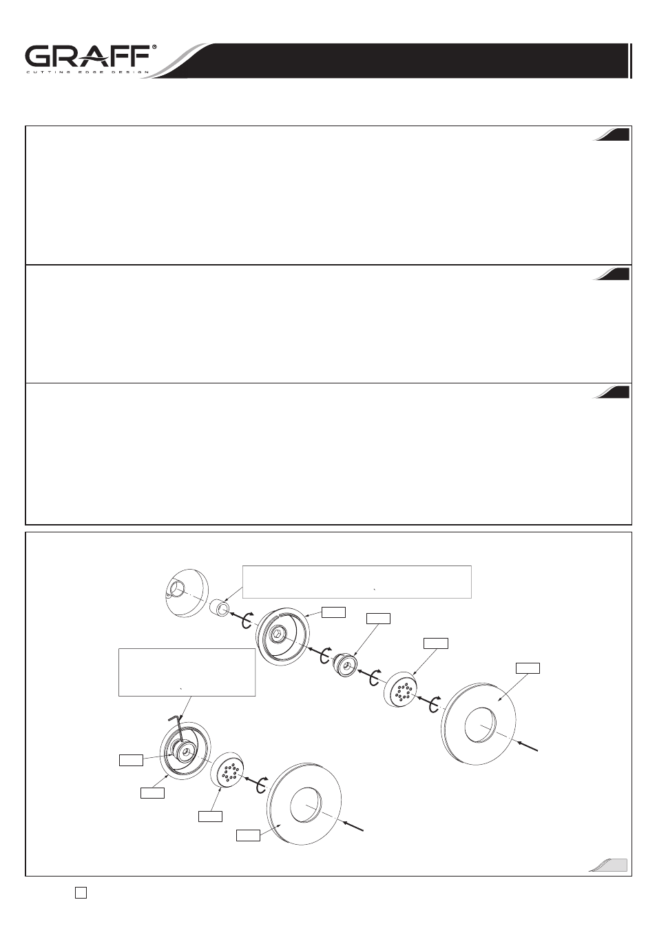
Użyj dołączonego klucza imbusowego
lub pręta o średnicy 3,5mm
Use hex key included or rod 3.5mm
Servez-vous de la clé imbus ou d’un segment
d’une barre de diametre de 3,5mm environ
Łącznik o odpowiedniej długości, wymaganej w Twoich warunkach montażu
The connector of a suitable length required for your assembly conditions
Un accouplement de la longueur appropriée a vos conditions de montage
T23
T23
T24
T24
T25
T25
T26
T26
Instrukcja Montażu i Obsługi
n
Instructions for assembly and use
n
Instrucción de Montaje y Servizio
14