ETC Net3 Two Port DMX Gateway User Manual
Two-port gateway installation guide, Overview, Installation requirements
Two-Port Gateway Installation Guide
Corporate Headquarters 3031 Pleasant View Road, P.O. Box 620979, Middleton, Wisconsin 53562-0979 USA Tel +608 831 4116 Fax +608 836 1736
London, UK Unit 26-28, Victoria Industrial Estate, Victoria Road, London W3 6UU, UK Tel +44 (0)20 8896 1000 Fax +44 (0)20 8896 2000
Rome, IT Via Ennio Quirino Visconti, 11, 00193 Rome, Italy Tel +39 (06) 32 111 683 Fax +44 (0) 20 8752 8486
Holzkirchen, DE Ohmstrasse 3, 83607 Holzkirchen, Germany Tel +49 (80 24) 47 00-0 Fax +49 (80 24) 47 00-3 00
Hong Kong Rm 1801, 18/F, Tower 1 Phase 1, Enterprise Square, 9 Sheung Yuet Road, Kowloon Bay, Kowloon, Hong Kong Tel +852 2799 1220 Fax +852 2799 9325
Service: (Americas)
(UK)
(DE)
(Asia)
Web:
www.etcconnect.com
Copyright © 2010 ETC. All Rights Reserved. Product information and specifications subject to change.
4261M2200
Revision D 2010-01
ETC intends this document to be provided in its entirety.
Page 1 of 2
Step 4.b
Overview
This Installation Guide will lead you through the setup of the Net3 Two-Port DMX/RDM gateway including
hardware, electrical and data connections. Software configuration of your gateway is covered separately
and relates specifically to the software versions that may be running in the gateway.
• For
Net3 configuration, please refer to the Gateway Configuration Editor (GCE) Online Help System.
• For use on
ETCNet2 systems, use the ETCNet2 Network Configuration Editor (NCE) User Manual which includes
information about the Net3 DMX gateways running in ETCNet2 mode.
Installation Requirements
•
Installation location - the Two-Port gateway fits into an industry standard 2-gang deep back box (provided by others) or surface-mount back box
(available by ETC).
•
Power - can be powered by either Power over Ethernet (PoE 802.3af) or by use of an external dc power supply. Power consumption is less
than 5 Watts.
•
For Power over Ethernet (IEEE 802.3af), connect to the RJ45 receptacle on the rear panel of the gateway. This connection point supports PoE,
auto-sensing, auto-negotiation and 10/100Mbps data speeds. All Ethernet wiring must comply with IEEE 802.3 and be terminated to the T568B
standard.
•
For DC power input (external power supply 8-28 Vdc), connect to the two pin pluggable header provided on the rear panel of the gateway.
•
An optional Universal Power Supply (ETC part number PS313-F) 90-240V AC to 12 Vdc @ 1.3 A is available for use with portable and rack mount
gateways. Contact your ETC Customer Service Representative for details.
•
Network Data and DMX - the Two-Port gateway complies with 802.3i for 10BASE-T, 802.3u for 100BASE-TX and 802.3af for Power over Ethernet
specifications. Data transport utilizes the TCP/IP suite of protocols and distributes DMX over Ethernet to any input/output device.
•
Ethernet is connected to the RJ45 connector on the rear panel of the unit.
• The Two-Port gateway is capable of supporting 1024 DMX In or DMX Out channels utilizing the two built-in DMX ports. The DMX ports can be
either two XLR-5pin Male DMX input connectors or two XLR-5pin Female output connectors. Termination switches are provided on the rear panel
for user convenience.
See page 2 of this document for more information on DMX and termination switches
.
Installation
ti
n
u
e
h
t
g
n
i
c
i
v
r
e
s
r
o
g
n
i
v
o
m
e
r
e
r
o
f
e
b
y
a
w
e
t
a
g
e
h
t
m
o
r
f
d
e
v
o
m
e
r
e
b
t
s
u
m
r
e
w
o
P
!
K
C
O
H
S
L
A
C
I
R
T
C
E
L
E
F
O
K
S
I
R
:
G
N
I
N
R
A
W
.
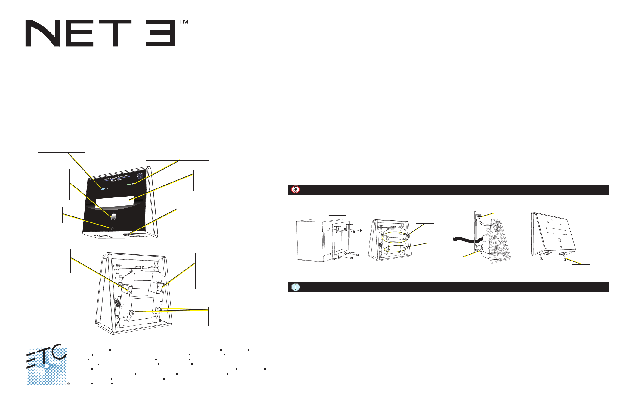
Reset button
• hard reboot
DMX Ports
• Pair of XLR 5-pin DMX Output
(female) or DMX Input (male)
connectors.
Step 1:
.
x
o
b
k
c
a
b
g
n
a
g
o
w
t
e
h
t
o
t
t
e
k
c
a
r
b
g
n
it
n
u
o
m
e
h
t
e
r
u
c
e
s
o
t
s
w
e
r
c
s
d
e
d
i
v
o
r
p
e
h
t
e
s
U
NOTE: This mounting bracket fits standard masonry wall back boxes, surface-mount boxes, and portable enclosures.
Step 2:
.t
i
n
u
e
h
t
f
o
l
e
n
a
p
r
a
e
r
e
h
t
o
t
a
t
a
d
d
n
a
r
e
w
o
p
e
h
t
t
c
e
n
n
o
C
Step 3:
e
h
t
s
l
o
rt
n
o
c
1
S
.
ti
n
u
e
h
t
f
o
l
e
n
a
p
r
a
e
r
e
h
t
n
o
d
e
t
a
c
o
l
s
e
h
c
ti
w
s
n
o
it
a
n
i
m
r
e
t
e
h
t
g
n
i
s
u
n
o
it
a
n
i
m
r
e
t
X
M
D
e
h
t
t
e
s
,
y
r
a
s
s
e
c
e
n
f
I
termination for Port 2 and S2 controls the termination for Port 1. By default termination is set to “On”. For most applications no
change to the default will be required.
Step 4:
.
x
o
b
k
c
a
b
e
h
t
n
o
t
e
k
c
a
r
b
g
n
it
n
u
o
m
e
h
t
o
t
y
a
w
e
t
a
g
t
r
o
P
-
o
w
T
e
h
t
ll
a
t
s
n
I
a: Align the top tabs on the Two-Port gateway to the receptacles on the mounting bracket.
b: Swing the bottom of the gateway down and hold it in place.
Step 5: Secure the Two-Port to the mounting bracket using the two screws on the bottom panel of the unit, next to the DMX ports.
Step 1
Step 2
Step 3
Step 4.a
Step 5
E
thernet (PoE 8
02.3af)
On
On
Menu Button
• Activates the
LCD backlight
• Advances
display pages
LCD
• Displays gateway status
and configuration data
Activity Indicator
• Solid green LED indicates
network connection.
• Flashing LED indicates
network activity
Power Indicator
• Solid blue LED
indicates power
DC Power input
• 8-28Vdc
• <5 Watts usage
Ethernet
• PoE (IEEE 802.3af)
• 10/100Mbps data speeds
• Auto-sensing
• Auto-negotiation
Termination
• DMX termination
switches