Terminate conductors, Smartlink enabled, Terminal output panel – ETC SmartPack Portable Pack with Terminal Output Panel User Manual
Page 2: N o t e, 3 phase install wiring
E T C S e t u p G u i d e
Terminal Output Panel
Terminal Output Panel Setup Guide
Page 2 of 2
Electronic Theatre Controls, Inc.
Terminate Conductors
Step 1:
Prepare the load conductors.
a: Strip 10mm (.39”) of insulation from the end of each wire.
Step 2:
Prepare the line conductors.
a: Strip 18mm (.71”) of insulation from the end of each wire.
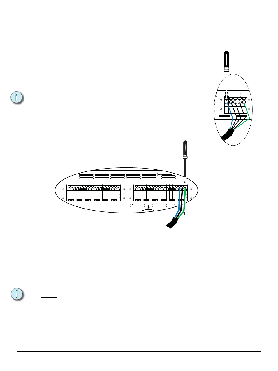
Step 3:
Connect conductors for Neutral, L1, L2, L3 and Ground as required
for single phase or three phase operation.
a: Align a 5mm (3/16”) slotted screwdriver with the top of the terminal
and press down firmly until the terminal gate opens.
b: Insert the proper wire into the terminal and remove the screwdriver.
The wire is held securely in place.
a: Align a 2mm (3/32”) slotted screwdriver with the top of the terminal and press down
firmly until the terminal gate opens.
b: Insert the proper wire into the terminal and remove the screwdriver. The wire is held
securely in place.
SmartLink Enabled
Two RJ45 connectors, labeled SmartLink IN and Thru, on the rear panel are for SmartLink™ pack to
pack synchronization. Reference the SmartPack Portable Setup Guide for pack to pack synchronization
setup, user interface overview and system test instruction. For operation and programming reference
the SmartPack User Manual.
N o t e :
Input terminals are rated for 65A maximum per phase.
N o t e :
The 3 channel 25 A Neutral Disconnect CE SmartPack Portable dimmer pack is
not SmartLink enabled.
N L1 L2 L3 E
3 Phase install wiring
G
1-L1
N
G
2-L1
N
G
3-L1
N
G
4-L1
N
G
5-L2
N
G
6-L2
N
G
7-L2
N
G
8-L2
N
G
9-L3
N
G
10-L3
N
G
11
-L
3
N
G
12-L3
N
Step 4:
Connect conductors for Load, Neutral and Ground
wiring for each load circuit. Circuit designations are
labeled on each unit and may differ from this graphic
depending on the model ordered.