Terminate wiring, Connect cat5 inputs, Final installation – ETC EchoConnect Cat5 Termination Box User Manual
Page 2: Terminate cat5 wiring
E T C I n s t a l l a t i o n G u i d e
Terminate Cat5 Wiring
EchoConnect Cat5 Termination Box
Page 2 of 2
Electronic Theatre Controls, Inc.
Terminate Wiring
Connect Cat5 Inputs
Stations that are installed for use with Cat5 control wire for the EchoConnect station bus are supplied
with a Cat5 Station Termination Kit (ETC part number 7186A1207). This termination kit includes all of
the parts and instructions that are required to complete EchoConnect station terminations when using
Cat5 cable.
The last station in the control run does not require use of the second 8 position IDC connector
(ETC part number J3409-F) provided in the Cat5 Station Termination Kit.
Use the second connector to
terminate the station data run to this
termination box. Refer to the Cat5
Cable Preparation for IDC
Termination Setup Guide
(4100M2202 revision D or later),
included with the Station
Termination Kit for cable
preparation and termination
instructions.
Step 1:
Connect the
prepared Cat5 cable
to any of the 16
available Cat5
receptacles in the
termination box.
Step 2:
Repeat for each
EchoConnect station
data run in the
system.
Connect EchoConnect to the Echo Station Power Supply
Step 1:
Run the EchoConnect cable (supplied Belden 8471 twisted pair) between this termination
box and the adjacent Echo Station Power Supply.
Step 2:
Remove the six position screw connector from the bottom position of the termination box.
Step 3:
Strip 3/8” (9-10mm) from each wire end in the supplied Belden 8471.
Step 4:
Maintain the wire twist as close to the connection as possible, then insert the white wire
into the data + terminal (1) and the black wire into the data - terminal (2) and tighten the
screws firmly onto each wire.
Step 5:
Replace the connector to the board.
Step 6:
Remove the two position screw connector from the Echo Station Power Supply
termination board.
Step 7:
Maintain the wire twist as close to the connection as possible, then insert the white wire
into the data + terminal (1) and the black wire into the data - terminal (2) and tighten the
screws firmly onto each wire.
Step 8:
Replace the connector to the board.
Final Installation
Replace the cover to the termination box and secure it in place using the six screws previously
removed. Reference the related station power supply installation documentation for power up and test
procedures.
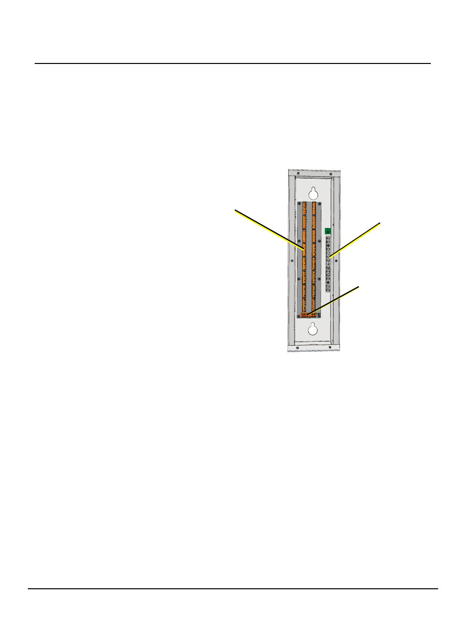
(16) Cat5
Inputs
ESD
ground bar
EchoConnect to
Echo Station
Power Supply