Installing the termination pcb, Connecting ethernet, Connecting linkpower and auxiliary power – ETC Unison Paradigm Rack Mount Touchscreen User Manual
Page 2: Paradigm p-lcd series
E T C I n s t a l l a t i o n G u i d e
Paradigm P-LCD Series
Unison Paradigm Touchscreen Rack Panel
Page 2 of 4
Electronic Theatre Controls, Inc.
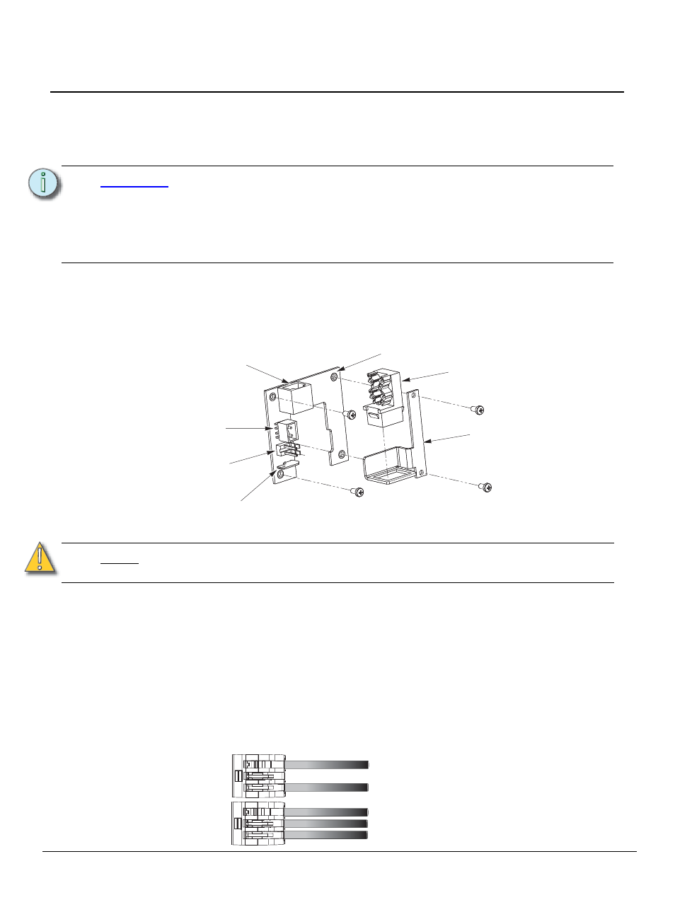
Installing the Termination PCB
The printed circuit board (PCB) assembly is designed to accommodate either Ethernet or LON
connections. Prior to installing the PCB, terminate all necessary wiring. The PCB is installed on the
back side of the rack panel.
The PCB consists of three parts:
• PCB with female RJ11, LinkPower connector, 24 Vdc (Aux) connector, and ground spade
• RJ45 with punch down wire termination
• Mounting bracket and screws
Connecting Ethernet
Step 1:
Terminate the network wiring in the RJ45 punch down strip using a standard 110 punch
down tool (not provided). Reference the connector label for the CAT5e wire termination
color code. The punch down connector provides insulation displacement. Do not strip the
wires.
Step 2:
Snap the RJ45 connector into the bracket.
Connecting LinkPower and Auxiliary Power
Use the provided WAGO CAGE CLAMP
®
connectors to terminate the wiring to the provided LinkPower
(black and white twisted pair) and Auxiliary power (red and black twisted pair) and ground wire pigtails.
Strip the ends of each wire (both installed control wires and pigtail wires) approximately 3/8” (10mm).
Step 1:
Terminate the installed LinkPower wiring to the white and black LinkPower pigtail. Using
two Wago connectors connect (typically white) installed wire(s) with white pigtail wire and
connect the (typically black) installed wire(s) with black pigtail wire as shown below.
C A U T I O N :
Only one network type may be connected to the touchscreen. Damage will occur if
both power types, Auxiliary power and PoE, are connected to the Touchscreen.
ETC requires that all backboxes are grounded in accordance with local electrical
codes.
The RJ11 connection must be used to provide a ground connection from the backbox
to the touchscreen even when Ethernet connectivity is used.
N o t e :
All Ethernet terminations must follow IEEE 802.3 and be terminated to the T568B
standard.
Ground spade
PCB
24 Vdc Aux
power
connector
RJ45
Mounting bracket
ULP connector
RJ45 Ethernet with
(PoE to Touchscreen)
RJ11 connector
(provides LinkPower and
Aux power to Touchscreen)
topology of a single
station installation
topology of multiple
stations installed in
series
Installed control wire
Pigtail wire
Installed control wire
Installed control wire to next station
Pigtail wire