Connect dali option wiring, Unison, Dali option kit – ETC Unison DRd DALI Option Kit User Manual
Page 2
E T C S e t u p G u i d e
Unison
®
DALI Option Kit
Unison DALI Option Kit Setup Guide
Page 2 of 2
Electronic Theatre Controls, Inc.
Connect DALI Option Wiring
It is important to label the DALI fluorescent ballast load and control wiring sets with the circuit
designation. Control wires terminate on the associated DALI board output loop terminal.
For example: If circuit 1 is configured as a D20 in DALI dimmer mode, DALI fluorescent ballast
control wiring should terminate to the DALI board loop output terminals labeled “1”.
Step 1:
Remove the DALI bus connector for loop outputs 1-6.
Step 2:
Strip each wire in the pair back 1/4 inch (6mm).
Step 3:
Using a jewelers screwdriver, loosen the terminals and insert each wire into the data
“+” or data “-” terminals for the specific circuit loop. Data wires in the wire set are
polarity independent.
Step 4:
Tighten the terminal screw until the wire is held snugly.
Step 5:
Repeat steps 1 through 4 for the remaining DALI loops through loop 6.
Step 6:
Replace the DALI bus connector on the DALI board and repeat for the remaining
DALI loops in the system (up to 24 loops).
*Maximum Run Lengths for Class 1 wiring
18 AWG
1mm
2
16 AWG
1.3 mm
2
14 AWG
1.6 mm
2
12 AWG
2 mm
2
**Max.
aggregate run
length
feet
meter
feet
meter
feet
meter
feet
meter
feet
meter
570
175
900
275
1,430
435
2,280
700
3000
900
*Maximum Run Length - the longest distance between any device and any power supply on the
DALI bus.
**Maximum Aggregate Run Length - the longest total length of all total wiring connected to the
DALI bus.
N o t e :
The associated output loop terminal number should always match the straight
power circuit numbering label inside the rack, regardless of straight or balanced
rack dimmer configuration.
N o t e :
DALI wiring can be run in the same conduit as the power wiring for the same
ballast.
2008
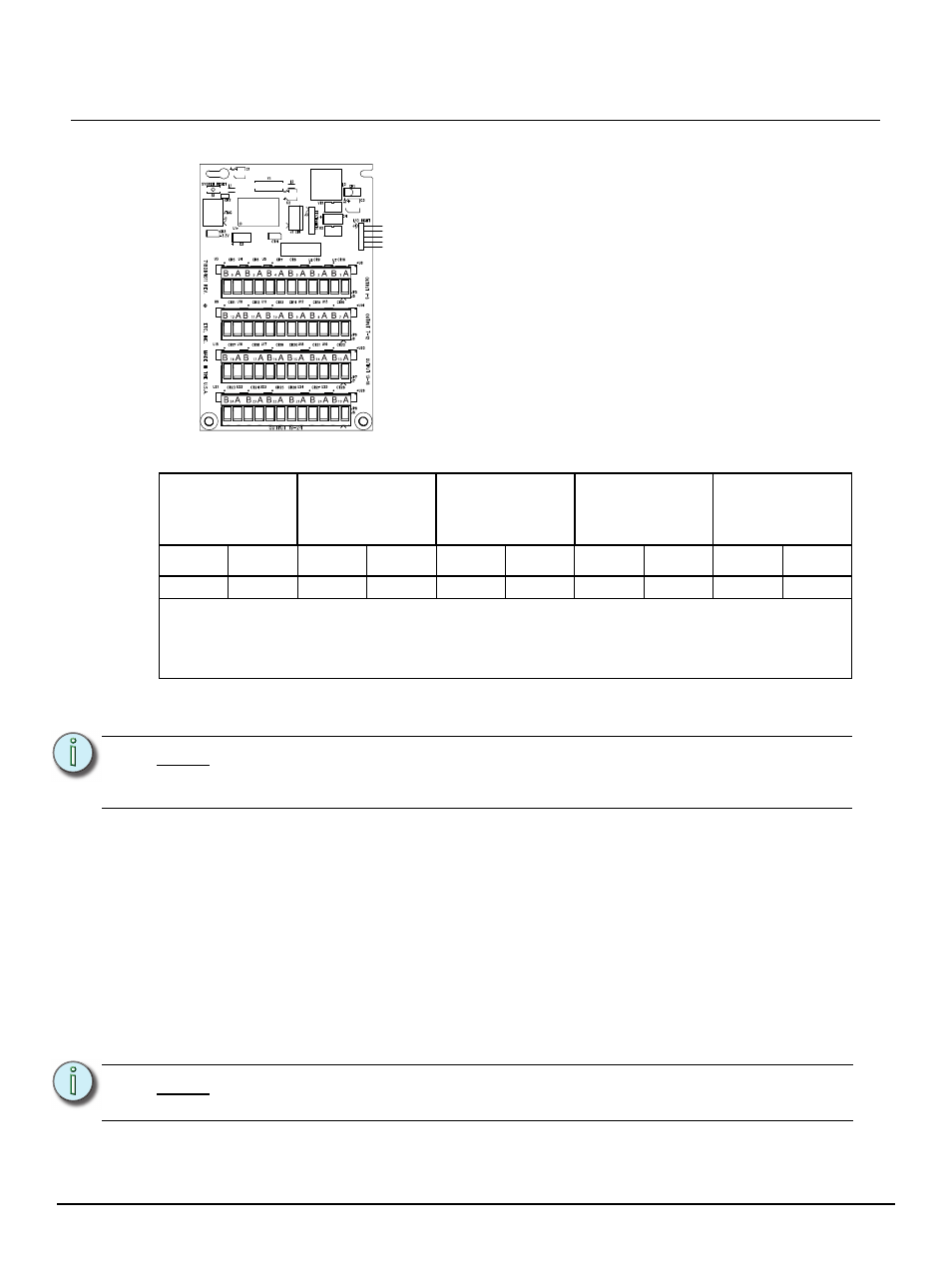
Each of the four bus connectors on the option board provide
termination for six DALI loops. Each bus connector is labeled
for ease of loop identification and is pluggable for ease of wiring
termination. Terminals accept 12-24 AWG (4 - .25mm
2
) Class
1 wire.